Data corruption in my TLC5940NT based LED cube (Solved)

I decided to make a 4x4 color LED cube, based on Great Scott's model, as my first ardunio project. Finished the cube and updated the code, something strange happens:

The code shows that the cube should be lighted up all LEDs with color changing, should be looked like Build your own RGB LED Cube Part 2: the electronics - YouTube in 5:07. But my cube only has 2 states, all white and all "off". Besides the wrong sequence, only the red part of the cube work properly, and some of the green and blue part of the LEDs switch on constantly.

Then I change another code, which turns 10 LEDs randomly, but again, only red part of the LEDs work fine, the same Blue and green constantly glow.

I have followed the circuit diagram except that I use 2 1k resistors instead of 2k due to lacking resistors of this value.

The connection of the serial IO: Ardunio > TLC5940NT > TLC5940NT> TLC5940NT

A photo is attached to show which LED is lit up constantly. ()

We are very sorry to hear that your cube does not work correctly. Because you give us so little information,I have only been able to find one error that you made:

I decided to make a 4x4 color LED cube... as my first ardunio project.

Although this is my first post and first project, I don't do nothing before making the cube, I have learned and understood some basic electronics (I am actually studing these kind of stuff at school) and ardunio stuff. I am sure I am understood MCU, LED, transistor, Multiplexing, etc before working on this project, the only thing I don't understand is what causes the data corruption of the cube.

I am going to give more detail about the problem:

Mentioned before, I attempt to make a circuit based on GreatScott's model, the file is attached as rar file.

At first, I use 64 common anode LED (I know what a common anode LED is, a LED has more than 1 cathodes but share by 1 anode), to form that cube and connected a wire and connectors. All of the LEDs have been tested(should a video is upload for proving?). So the LED itself work fine, I am not going to talk much about it.

But the problem is the circuit itself, I followed the schematics:
5v to Vcc;
Ground and VPRG to common ground;
IREF (for setting reference current) to ground also, but adding 2k resistor in between them;
GSCLK, Blank, SCLK, XLAT are connected their corresponding io pins;
Sin for the first TLC5940NT is connected to D11 pin;
While others connected to the previous Sout due to sending serial data;
.
.
.
After finishing the circuit on the breadboard, I test the serial signal transmission of the TLC5940NT, so I just connect all layers of anode to Vcc first, ignore those Mosfet and multiplex stuff, assume that they are just a 4x4 matrix but it has 4 layers. I use the source code obtained from GreatScott's 4x4 LED cube tutorial.
The code mentioned that the cube will display in the following sequence:
All LEDs: Red > Green > Blue > Cyan > Yellow > Purple > White (Even there is no multiplexing, the display is still the same due to switching all the LED to same color)

But I only get this strange sequence:
All White > 6 LED off and rest of them are blue or green (The photo I have shown before and consider there is only 1 layer due to connecting all anode with no Mosfet)

Do I need to record a video about the problem?
And what kind of information should I upload?

RGBLEDCube GreatScott!.zip (124 KB)

Many forum members read the forum on smartphones & tablets for much of the time, including myself. So cannot open zip/rar files. Please post schematics and pictures as jpg or png files and insert code into your post between code tags. If you read the "please read" post at the top of each forum section will explain how to do those things and gives many other useful tips to get the most help from this forum.

If I sound too ignorant and arrogant, I apologize.
I am not a native English speaker, I am struggle to get the wording sound natural and valid(I am really tring to get the tone right), feel sorry about wording may sounds too stupid and immature. :frowning:

I know LED cube is a little hard for people who start making things using Arduino, I also know the risk of failing to make this "toy", if anyone thinks I am too arrogant for this, please tell me to stop, I will continue to make this if I learn more about this kind of stuff.

I am not sure is it valid to upload someone else's stuff; anyway, GreatScott's schematic and part of his code will upload in a non-zip format:

ledcube

#include <Tlc5940.h>
#include <tlc_animations.h>
#include <tlc_config.h>
#include <tlc_fades.h>
#include <tlc_progmem_utils.h>
#include <tlc_servos.h>
#include <tlc_shifts.h>

//http://www.youtube.com/user/greatscottlab 

#include "Tlc5940.h"  //don't forget to download the Tlc5940 lib from arduino playground ( http://tlc5940arduino.googlecode.com/files/Tlc5940_r014_2.zip )
#define LayerOne 14      //Gate of 1.MOSFET which connects to Layer "a" (anodes of all Strings in Layer "a")
#define LayerTwo 15      //Gate of 2.MOSFET which connects to Layer "b" (anodes of all StringS in Layer "b")
#define LayerThree 16    //Gate of 3.MOSFET which connects to Layer "c" (anodes of all Strings in Layer "c")
#define LayerFour 17     //Gate of 4.MOSFET which connects to Layer "d" (anodes of all Strings in Layer "d")


int LayerDuration = 4000;     // ON time of each Layer in microseconds  
int layer = 0;                // starting with Layer 0 (Layer "a")
unsigned long oldMicros = 0;// starting counter to decide when if(micros()>=oldMicros)is true to change active layer, count++1, MatrixUpdate(); don't know what micros() is? Look here: http://arduino.cc/de/Reference/Micros#.UygzAIWmWd4
int count=0;                // starting counter which is included in if() statement to change the shown picture, not necessary when using a static picture
int stretch=200;             // set timer for the change of the shown picture, if animation should move really fast then low stretch value, if animation should move really slow than big stretch value
int bright=3000;            // set brightness for all Strings(4095=20mA, 0=0ma, 1000=4.88mA,....). If you want individually brightness for a String you have to change the value in tab "function"


void setup()
{
  pinMode(LayerOne, OUTPUT);  // declare arduino nano pin A0(LayerOne) as OUTPUT
  pinMode(LayerTwo, OUTPUT);  // declare arduino nano pin A1(LayerTwo) as OUTPUT
  pinMode(LayerThree, OUTPUT);// declare arduino nano pin A2(LayerThree) as OUTPUT
  pinMode(LayerFour, OUTPUT); // declare arduino nano pin A3(LayerFour) as OUTPUT
  Tlc.init();               // configures the arduino to use the tlc5940, be sure to connect the arduino correctly to the tlc 
 
 /*          ARDUINO                                         TLC5940                            
              13|-> SCLK (pin 25)           OUT1 String "B" |1     28| OUT0 String "A"
              12|                           OUT2 String "C" |2     27|-> GND (VPRG)
              11|-> SIN (pin 26)            OUT3 String "D" |3     26|-> SIN (pin 11)
              10|-> BLANK (pin 23)          OUT4 String "E" |4     25|-> SCLK (pin 13)
               9|-> XLAT (pin 24)           OUT5 String "F" |5     24|-> XLAT (pin 9)
               8|                           OUT6 String "G" |6     23|-> BLANK (pin 10)
               7|                           OUT7 String "H" |7     22|-> GND
               6|                           OUT8 String "I" |8     21|-> VCC (+5V)
               5|                           OUT9 String "J" |9     20|-> 2K Resistor -> GND
               4|                          OUT10 String "K" |10    19|-> +5V (DCPRG)
               3|-> GSCLK (pin 18)         OUT11 String "L" |11    18|-> GSCLK (pin 3)
               2|                          OUT12 String "M" |12    17|-> SOUT (only used when you want to use more than one tlc5940)
               1|                          OUT13 String "N" |13    16|-> XERR (can be used as error report, but not necessary)
               0|                          OUT14 String "O" |14    15| OUT15 String "P"       */
  }

void loop(){
  
  if(micros()>= oldMicros){                                           // waits until LayerDuration is reached and than goes through cycle
    oldMicros=micros()+LayerDuration;                                 // updates oldMicros value by adding the micros() with LayerDuration
   if(count==0){reset();allred();}                                    // shows first static picture when count==0, so right at the beginng
   if(count==stretch){reset();allgreen();}                            // shows second static picture when count==2*stretch
   if(count==2*stretch){reset();allblue();}                           // .
   if(count==3*stretch){reset();allgreen();allblue();}                // .
   if(count==4*stretch){reset();allgreen();allred();}                 // .
   if(count==5*stretch){reset();allred();allblue();}                  // .
   if(count==6*stretch){reset();allgreen();allred();allblue();}       // .
   //if(count==7*stretch){reset();}                                   // .
   //if(count==8*stretch){reset();}                                   // .
   //if(count==9*stretch){reset();}                                   // shows 10. static picture when count ==9*stretch
   CubeUpdate(layer);                                                 // sets the values for the tlc5940 Outputs and puts all MOSFET Gates HIGH (not active) except for one MOSFET Low (active) -->this layer is ON, also look under tab "function"  
   layer++;                                                           // layer counter +1, so MatrixUpdate(layer) will affect the next layer during the next if() cycle 
   count++;                                                           // count counter +1, to change the picture in next if() cycle
   if(layer==5){layer = 1;}                                           // we only have 5 layers, so we start with layer 1 again if layer counter goes to 6
   if (count==7*stretch){count=0;}                                    // we have 8 static picture for the moving sine wave, so if count counter would hit the 9.(not existing) pic, it goes back to count=0
   }}

I don't think this well-known YouTuber did make any mistake but me, I don't know am I mistaking on building the circuit or buying the fake chip (I bought 5 atmega328p that doesn't work, only RX flash 3 times and error shown on the ide, then I realize the chip is fake :cry: ).

I provide the pinout of the TLC5940NT anyway:

Since I have oscilloscope and multimeter also, if anyone who has experience on using this chip, please tell me which pin should I measure for coping with the data corruption problem.

I know I may still providing not enough information, please reply if any extra information is needed.

Your Sincerely,
Digital Soundwave

I think its OK to upload other people's work, as long as they have released it as open source and you give their name and give them the credit, and a link to where you found it.

So are you saying that you have copied/followed GreatScott's circuit and code without any changes? Then I would say wiring errors or bad solder joints would be my first suspects. Did you test every led? Is is possible they were purchased cheaply from eBay and you have been sent a mix of common anode and common cathode? Many eBay sellers are ignorant of those terms and the difference between them.

Describe your testing process again in more detail. Did you perform tests where no multiplexing was performed and only one layer was tested? Were you able to get all leds on a single layer to light together in red/green/blue/yellow/cyan/magenta/white? And then repeat that test for the other 3 layers?

You have no decoupling capacitors on those chips. Each one need a 0.1uF ceramic capacitor between power and ground of the chip. See:- De-coupling

PaulRB,

I have followed his diagram, except for 2 differences:

  1. Uno is used instead of nano;
  2. 2 1k-resistors representing those 2k resistors

I know I have made a big mistake about not testing on the breadboard at the first try, but I have done it after the cube doesn't work. Even I use the breadboard, the same glitchy graphic still occurs. Perhaps I have to check the wiring a few more times to see that any mistake I have made later.

Talking about LEDs and eBay, It is ridiculous to hear about seller randomly mix those common anode and cathode LEDs in a single bag... Fortunately, every time I buy components and other stuff, I have always checked the comments about the shop (Since I use another platform to buy stuff) to make sure the shop is reliable. Even I received those products, I always check those components is working or not (except those 5 atmeag328, sigh...). Before I make the LED cube, I have also checked all 64 LEDs are common anode and working flawlessly, since I don't want to desolder a broken LED in a finished cube. After forming the cube, a voltage source is used for testing the cube, positive to anode and corresponding cathode pin to ground, all 64 LEDs light up nice and bright.

The testing process of the circuit:
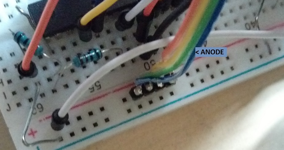
Since I know the circuit doesn't work, I unplug all LED driver from the circuit and put into a breadboard, and I followed the circuit diagram to reproduce another circuit.(photo 1, I have to send it as an attachment).
Since I have not enough jumper wires and space, I decided not to build the multiplexing circuit (the 4 MOSFETs and the remain io pin from the ardunio). I just assume that is just a matrix(top view), so I connect all anode to Vcc( technically all LEDs light, but received signal of all 4 layers per layers). Since the animation from the source code is simple, it is no difference for displaying 4 layers individually or in a single layer instead.
(I will try to light up individual layers also, to observe any differences)

In theory, the LEDs should show up in the following sequence:
(Top view. Sorry, I can't provide the following image at the time)
RRRR GGGG BBBB CCCC // C = cyan
RRRR > GGGG > BBBB > CCCC
RRRR GGGG BBBB CCCC . . . (with all the other color)

But the result what I get was:
WWWW XXCG // X = no light
WWWW > XCCG
WWWW > XCCX // 2 LEDs have unusual blinking when
WWWW XCCX // turning white ([4,3] and [4,4])

If I unplug all the connector except for the specific TLC5940NT output I wanted to test, it has the following result (T and F this time, since the color of the LED have no effect for the following result):

The first TLC5940NT output (signal received from the ardunio):
TTTT FFFF
TTTT > FFFF
TTTT > FFFF
TTTT FFFF // this is the part works normally

Second TLC5940NT output (signal received from the first TLC5940NT's SOUT)
TTTT FFTT
TTTT > FTTT
TTTT > FTTF
TTTT FTTF

Third TLC5940NT output (signal received from the second TLC5940NT's SOUT)
TTTT FFTF<-- sometimes these
TTTT > FTTF<-- 2LEDs light up also
TTTT > FTTF
TTTT FTTF

In combining the random LEDs function I did in the very first post, it is believed that the first LED driver gives a correct signal, but the following drivers don't. I even swapped all three LED drivers, but the result was unchanged.

Grumpy_Mike
OK, I will try this later. A reply will be sent after the this method has been tested.

I just assume that is just a matrix(top view), so I connect all anode to Vcc( technically all LEDs light, but received signal of all 4 layers per layers). Since the animation from the source code is simple, it is no difference for displaying 4 layers individually or in a single layer instead.

I didn't understand that.

T and F this time, since the color of the LED have no effect for the following result

Or that. Quite a few things that you said in your last post were difficult to understand.

After forming the cube, a voltage source is used for testing the cube, positive to anode and corresponding cathode pin to ground, all 64 LEDs light up nice and bright.

What no current limiting or a resistor?

A bit like striking matches to see if they work.

Oops... I think some images is needed for helping me to explain.

After I use solder the frame of the LED cube, connector soldered. Then I use voltage source and limit the current around 0.1A(I just recently found that I may set too much current). When I test every single LED working or not, I did actually do something like Mike mentioned. Is it not a valid way to test the LEDs?

Back to the part I don't explain clear or make anyone feel confused.

T and F stand for "True" or "False", meaning that the LED is "on" or "off"

The 4x4 matrix of letter is about the pattern change of my LED cube in top view, but I am going to post the photo instead since I have took some recently.

The following attachment is related the that "Matrix thing" I have drawn before. (I don't know how to
show the photo if the photo is not from website):

First TLC output - all off: The photo shows the corresponding TLC out pin, and the TLC that receiving signal from the ardunio, it should be all off,

First TLC output - all on: All LEDs are switch on

Corrupted output from the remain TLC5940: Then I switch the connector to another set of TLC's outputs(Serial in signal received from the first TLC5940 ),
Some of the lights switch on but it shouldn't. (The another state of these output is same as the "All on photo")

Anode connect to Vcc: The photo shows that I connected all the anode to Vcc, so there isn't any multiplexing going on, meaning that display of every Layer is identical. Since all layer display the same image, only the top layer is used for references. This is what the assuming it is just a 4x4 matrix came from in the earlier post.

Besides, I also add some decoupling capacitors, but it make no difference, so It might be another problem.

Besides, I also add some decoupling capacitors, but it make no difference.

Then they were not position correctly. These capacitors are not an option they must be included.

OK time to step back. You have a mass of wires on a solderless bread board and a mass of code. You are trying to do too much at one time and you haven't got the skills to sort it out. The conditions you describe are not helpful and just contain too much unnecessary detail.

Corrupted output from the remain TLC5940:

So that is what you have to address first and foremost. Just use one TLC5940 with one of the sets of the anodes permanently connected to the supply.
With this setup try the walking LED code and see if the TLC is outputting correctly. If not your problem is either connections or supply decoupling. Get that going first before you try and implement anything else. Without any multiplexing and with all the LEDs enabled then you will be drawing too much current through your TLC5940.

Grumpy_Mike:
You are trying to do too much at one time and you haven't got the skills to sort it out. The conditions you describe are not helpful and just contain too much unnecessary detail.

I think I find my answer. Right, maybe I should stop this for awhile, and learning something simpler, like how those chips works, how to make a matrix using shift register, signal transmissions, escepially how to explain things clear.
I finally know what makes dunning effect terrifying.

I know the problem doesn't solve at the time, but I am still thanks all of you who try to help.

Maybe the post should stop until something new happened.

PS: I don't notice the sample code in the TLC5940nt library, I should use them to understand how to use these chips before I start to make the cube.

Update:
I am a [muted] idiot, when I go to a website called Tonixstuff and I saw something:

open the file tlc_config.h located in the TLC5940 library folder. Change the value of NUM_TLCS to the number of TLC5940s you have connected together...
(tronixlabs,21 October 2013)

Then I open the code, and I found this...


I don't set the NUM_TLCS to 3...

After I set the right value:

It works! ... :cold_sweat:

Well done!