Datalogging with power-loss protection & How to make a battery backup circuit if mains fails (using mosfet)

Great, thank you!

I've since learnt 2 more things;

  1. Energizer ultimate lithium has a very flat discharge curve, meaning voltage stays mostly constant throughout the lifetime and then plummets down before death. Looking at graph on the datasheet, max voltage will be 5.1V (1.7*3) with 3 batteries, and minimum is around 4.5V (1.5v * 3). Therefore, I will only need a buck regulator, and not a buck-boost regulator to get to 3.3v.
  1. I have found that I actually have an SMD p-channel mosfet (AO3401) that has a minimum Vgs(th) of -0.5V, so this will completely eliminate the chance of being turned on if mains power returns... provided all the batteries are infact at 1.8V (5.4V total) in the worst case.

i.e. the vgs of -0.4 = (5v - 5.4v) is greater than vgs(th) min of -0.5V, so definitely OFF.

Max drain current of that MOSFET is 4 amps, so that seems plenty.

However, the mosfets are from Aliexpress, so maybe the figures aren't very trustworthy.

I think that covers everything, except that this person seems to think that the mains power could still try to charge the battery, which has me a bit confused, as I thought the internal mosfet diode prevented that completely; P Channel MOSFET to do automatic switch between battery and power source - Electrical Engineering Stack Exchange

thanks again!

He has the mosfet oriented backward. So his body diode would let the mains supply through to the battery. But if you connect the drain to the battery and the source to the load, the body diode will protect the battery so long as the mosfet is off. Note that a mosfet will conduct pretty much equally well in either direction if it's turned on.

ahhh ok, makes sense. So when mains power is powering the circuit, we need to make sure that the mosfet is completely off, so as to not have the mains voltage flow into the battery.

If mains power gets restored into the circuit that has been powered by battery, but the mosfet does not turn off completely, then this would cause the DC mains to flow into the battery and charge it.

However, I also forgot about the Schottky diode which will reduce the mains DC voltage to maybe 4.7V at the source, and since the 3 * energizer ultimate lithium batteries will take a while to drop below 4.7, I think that means there's even less of a chance of the batteries getting charged

I'm thinking that a simple way to test if the Mosfet is doing its job is if you measured the current between the Drain and the Positive of the battery. If mains DC is turned on, but there's current flowing at this point, then mosfet is actually on when it should be off. I could adjust the battery voltage between 4.5V (lower end) and 5.4V (higher end) to see if everything works at all these ranges.

Also, if I have the fully charged battery pack at 5.1V at the drain and the mains DC of 4.7ish volts at the source, then I could measure the voltage at the source and make sure that it is only 4.7V when the mains is on. If the Mosfet is on when it's supposed to be off, then I'm guessing that a higher than 4.7V figure will show up at the source, as now the higher battery voltage of 5.1V is flowing.

I could also do this the other way around if I set the battery voltage to 4.5V and the mains voltage remains at 4.7V at source. If mosfet is on when it's not supposed to be, then I think that a higher than 4.5V will show up at the drain.

You've been really damn helpful with this topic, so I I'm going to change the title of the thread so people can find it easier!

You could also insert a very low value resistor between the battery positive terminal and the drain, and measure the voltage across it (which is what your meter does when measuring current). If the voltage ever goes negative, that means current is flowing back into the battery. And if it ever goes positive when the mains supply is present, that means battery current is flowing when it shouldn't (see below).

But without disturbing the circuit, you can measure the gate/source voltage. It should never go more negative than -0.3V if the mains source is present. That will automatically take into account whatever drop you get across the Schottky diode.

The other situation you want to avoid is where the battery voltage is enough higher than the mains supply that the battery powers the load through the body diode even if the mosfet is off. If the battery is 5.7V, then that would be about 5.1V after the body diode drop. And if the mains voltage is 5.3V, that would be 5V after the Schottky drop. At that point the gate would be 5.3V, and the source would be 5.1V, so the mosfet would be completely off, but the battery would be powering the entire load through the body diode. So basically this circuit works when the mains voltage is higher than the battery voltage. You have a little leeway on that, but not very much. The leeway is the difference between the body diode drop and the Schottky diode drop. Essentially, if the mosfet is off, the circuit becomes a basic two-diode circuit.

I see, thanks. well in the worst case that the 3 batteries are 1.8V (5.4V total) and the typical Diode Forward Voltage (VSD) of the AO3401 is 0.7V. That gives me 4.7V.

My mains supply is 5v. After the Schottky drop that becomes 4.7.

So battery and the mains are both 4.7V after the drop = presumably not good.

But in the typical case that the batteries will actually be 1.7V each, then this becomes 5.1V before drop and 4.4V after the drop.

So mains is now 0.3V over and we don't get the battery powering the circuit when the mosfet is off. All potential problems solved...I think :rofl:

Yes, I think so too. You just have to check the voltage of the mains supply under load to make sure it stays at 5V or very close to that.

Thanks! Super interesting stuff.

If it doesn't work reliably though, perhaps due to the aliexpress Mosfet being junk, then I think the obvious solution would be to either bump up the mains voltage, or bump down the battery voltage and use 2 x AA batteries (3.6V max, 2.8V min) and run both voltage sources through a step up/step down 3.3v regulator.

I think it will work ok as long as your mains supply is 5V. The downside of a buck/boost converter is that it may not be very efficient. And I'm not sure what you would find in the way of buck/boost modules that can output 3.3V. So if it's flaky at the margins, I would look for a way to increase the mains supply voltage a bit if that's possible. The big question is how much the voltages will droop under load. I've forgotten - did you say how much load current you will have?

I haven't figured out the current yet, but I made an overestimation that it would peak at 1 amp, as I read that the esp32 can spike to 750 mA with wifi and an Sd card can get to 200mA. More than likely never going to get that high

So I figured a 1 to 2A 3.3V LDO is the way to go. Yeh I definitely think I should just forget about the buck/boost stuff and just increase the mains voltage a bit if the setup wont work.

Or, I could solve all these problems by getting an expensive "prioritised powerpath controller" IC, of which there are only 5 left in stock and wont restock until 2023 :rofl: https://au.mouser.com/c/?marcom=117315649 big nope.

Parts like that are above my pay grade.

However, looking at the datasheet for that LTC4421, the Typical Application circuit illustrates one way to deal with the body diode issue. You'll see that they use two mosfets in series, oriented so the two sources are connected together, and the two gates are also connected. So both mosfets turn on and off together, but their body diodes are oriented in opposite directions. So when the mosfets are off, no current will flow through the diodes in either direction. One or the other will always block the flow. The downside is that you have twice the On resistance through the mosfets. But Rds(on) on mosfets these days is so low that that may not make any difference.

But looking at that circuit, it shows how much more complicated and parts-hungry it can get when you need to prioritize one supply over the other even if the priority supply has a lower voltage. Things are so much simpler if the priority supply always has the higher voltage.

Yeah! That schematic was a headache to look at, but It's good that you mentioned it because I actually bought a few cheap LTC4412's (not to be confused with the LTC4421 that you looked at) from Ali today, as the datasheet gave a really thorough example of a "lowest-loss" battery switching setup (with the mains higher than the battery).

I might have to run the math on it better, but it sounds like it work very efficiently with a 6V mains and 5.1V battery supply, in both a mains disconnection, as well as a mains reconnection event, using 2 x AO3401 Fets.

Then they give an example using the back-to-back P-fet connection you mention, which can be used with the auxiliary battery power being higher than the mains power;

Except you need to have the microcontroller actually monitor the voltages of both power sources, to see when the mains power is falling (preferably through a voltage divider), and once power loss is detected you switch the state of the CTL pin.

I'm guessing you could have the process done autonomously if you had a comparator.

Well, when your parts come in, I hope you'll report back what you ended up doing.

will do!

Hi @ShermanP. As promised, here's an update on the battery backup circuit (using P-Fets) I'm trying to make.

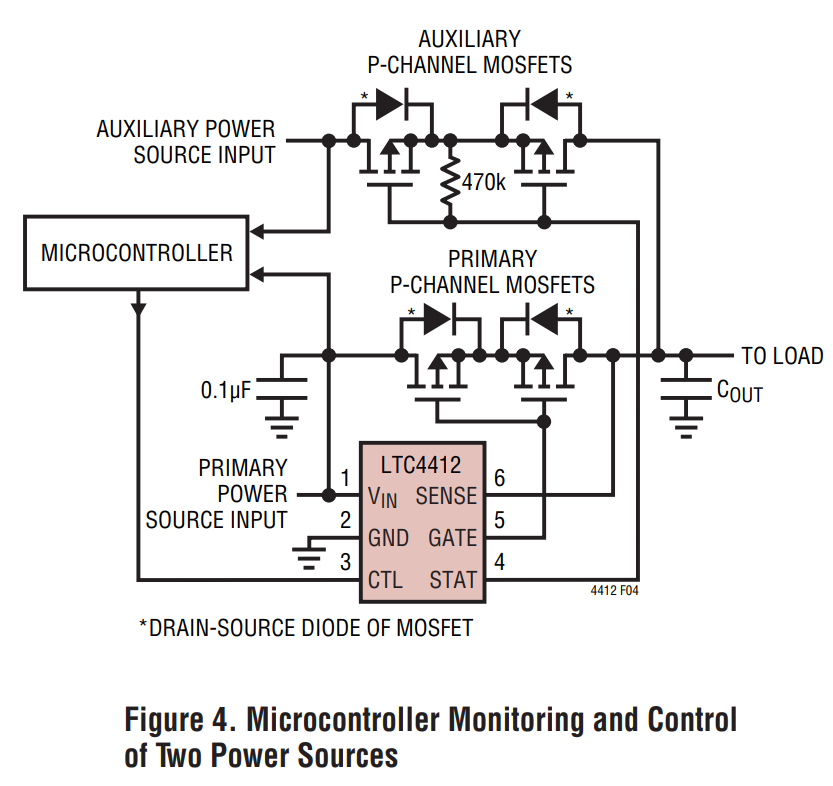
My LTC4412’s have arrived and I’ve tested both the “Automatic PowerPath Control” and the “Ideal Diode Control with a Microcontroller” example’s from the datasheet, which are both pictured in post #32.

LTC4412 datasheet; https://www.analog.com/media/en/technical-documentation/data-sheets/4412fb.pdf

They both work great.

Despite the fact that it’s more component hungry, I’ll probably go with the “Ideal Diode Control with a Microcontroller” example, as it allows the auxiliary voltage to be higher than the mains voltage. This gives only a very slight loss of efficiency, as RDS(on) is indeed very low. That’s also a lot more efficient than using a Schottky diode as an OR-ing circuit, by my calculations.

I’ve mostly replicated the circuit from the datasheet, but I added in an NPN transistor and an Op-amp as a voltage comparator (Op-amp is not pictured). I am also now using 4 x AA batteries, which gives a battery voltage of around 6.8V.

The first picture is the original schematic from the datasheet, and the second picture is my small addition of an NPN transistor between the STAT pin and the gate's of the Auxiliary Fets.

The way my full circuit works is that once the 5V mains PSU drops to 4.5V (which would indicate a power loss), the Op-amp comparator circuit (not pictured) sends a signal to an interrupt pin on the ESP-32, and the ESP immediately sets the CTL pin on the LTC4412 to HIGH. This causes the Auxillary battery power to take over, as the STAT output pin (open-collector) switches to LOW.

However, if mains power returns, setting the CTL pin back to LOW will not actually get the 5V mains power to take over again. This is stated in the datasheet. 5V Mains power will only come back if both the CTL pin is LOW and the battery voltage falls below mains voltage.

So to solve that problem, I’ve added in an NPN transistor (T1). When the NPN transistor is turned on, it provides a path to ground (via the STAT pin) for the Auxillary P- Channel Mosfets, so that if the STAT pin goes LOW, the Auxillary P-fets can turn on. When the NPN transistor (T1) is turned off, it disconnects the P-fets from ground, which cuts the battery voltage and reconnects the 5V mains voltage (provided CTL is LOW).

That same NPN transistor can also allow me to automatically cut power to the ESP32 when I've backed up everything to the SD card (provided mains power doesn't return in time), which is what I intend to do.

It's also worth mentioning that there's a small delay (few seconds) in Setup when the MCU first turns on, as the under-voltage signal will be triggered when the power supply is first turned on.

The 470K resistor R1 in the original example acts to pull-up the STAT pin, so I added another resistor, R2, to also pull-up this stat STAT pin up when the NPN transistor (T1) is turned off. Not sure if it's necessary, but I don’t think it will hurt. I think that 470K resistor is also used to keep that gate of the Auxiliary mosfets HIGH when they are not connected to ground.

I’ve tested this exact circuit and it works very well and consistently. It is so fast that it works without using a capacitor (capacitor is used to keep the circuit alive while the switching takes place), though I’ll add one anyway.

I know you said you're not familiar with the the LTC4412, but is there any problems you can see with my addition of the NPN transistor to the circuit, or other feedback?

Thanks!

It looks pretty good. The thing I wonder about is the NPN. Since I have no experience with the LTC4412, I don't quite understand the datasheet entries concerning the STAT pin. It says the STAT sink current has a typical value of 10uA, and a maximum of 17uA. Does that mean it can't sink more than that? That seems unlikely. The first 470K resistor would use 10uA, and the second one you've added would put you over the maximum. So if you have the NPN base resistor at 1K, how much base current will flow when STAT goes low (the base current will also flow through STAT). If the sink current is really that low, I don't think STAT could pull the gates low. Have you measured that? What is the gate voltage on the aux mosfets when the NPN is turned on and STAT is low?

Would you consider using an N-channel mosfet like the 2N7000 or BS170 instead of the NPN?

On further reflection - first, I don't think you need R2. Unless STAT is low and the NPN is turned on, the original R1 should work. At any other time you'll be pulling the gates low anyway, and an extra pullup resistor won't do anything useful, and could mess up the STAT current limit (see below).

On reading the datasheet further, it appears the STAT pin sinks a nominal 10uA when it goes low. So that really is the limit. If you use the NPN, when STAT goes low and the base goes high, the collector voltage will be about one diode drop below the output High voltage of the processor GPIO pin. So for an ESP32, that would be about 2.7V. That brings the gate voltage low enough to turn on the mosfets. Probably. But it also depends on the gain of the NPN. And it also assumes I'm right about how the NPN behaves when its emitter current is limited to 10uA.

So I really think the NPN should be a mosfet instead, which would let STAT draw the gates almost to ground when the controller turns it on. The only issue is possible leakage current when it's off.

Also, if you could be sure the battery voltage would always be higher than the external power source, could you just switch the two sources and not need the NPN? I mean, the designation of prmary and auxilliary sources is arbitrary isn't it?

Thanks for looking further into it!

Good point about potentially measuring the current draw from the STAT pin, to make sure it doesn’t exceed the maximum rating. I will try to do that with a multimeter.

I'm not fully understanding the voltage drop problem with the NPN transistor unfortunately, but I think what you’re saying is that using an N-channel Mosfet would reduce the voltage drop to almost nothing when it’s turned on, so that would provide a path to the STAT pin that is closer to ground. The 2N7000 seems to suit this application as it has a low VGS(th). Is this how I would wire the N-FET?

Ahhh good point. Looking at the datasheet for 2N7000, the Zero Gate Voltage Drain
Current (IDSS) is 1 µA.

As per the application example, you can switch the voltage sources between a lower voltage primary source and a higher voltage auxiliary (or vice versa), through setting CTL to HIGH, but after that switching takes place, you cannot switch from the higher voltage auxiliary back to the lower voltage primary. The switching back to primary can only happen when the primary voltage is higher than auxiliary, and the CTL pin is switched back to LOW. Therefore, there needs to be some way to get the Auxiliary voltage back to 0v, so my idea was to force those Mosfets to turn off through the NPN transistor.

Well, I don't think you can actually exceed STAT's current limit. It's apparently designed to sink 10uA while maintaning the voltage near ground. If you try to sink more than that, it will just make the voltage rise.

Well, an NPN is a current-based amplifier. The collector-emitter current is the base-emitter current times the gain of the transistor. But there is the additional complication that there is a one-diode voltage drop from base to emitter. So the base-emitter voltage has to be at least 0.6V for any current to flow. And with a 470K collector resistor and a 10uA emitter current limit, when the GPIO pin goes to 3.3V, I think the emitter is going to be at 2.7V. If it were higher than that, no current would flow, and if it were lower than that the base feed would bring it back up to that. And that means the collector voltage will also be close to 2.7V. With the gates at that voltage, will the mosfets turn on? Well they certainly would at 6.8V battery voltage. But what if the batteries have discharged to 4.8V? Will the Vgs at that point still turn them fully on?

The mosfet simply avoids all of that because it's voltage based. You drive the gate high enough and the mosfet turns on - without adding any additional current burden to STAT. Yes your drawing looks fine, but you need to think about how you want things to behave when you first power up. The GPIO pin will be floating until the ESP32 has booted up. How will the ESP32 get power during that period if the external supply isn't there? What will turn on the battery supply if the mosfet, or the NPN, is off?

On the subject of leakage, the only leakage would be into the STAT pin, which will be floating anyway, so I don't think leakage matters.

You've studied the datasheet more than I have, but I remember it differently. I think the voltage comparisons only applied to one way of switching, but the other way wasn't dependent on voltage. Well, I'll defer to your memory, but would just suggest you go over that paragraph again to be sure. I think the NPN or mosfet is going to complicate things. So if there's any way to set it up so you can switch to the external supply whenever it's present, that's really all you need it to do.

Ok, well to prevent the NMOS from ever floating on start-up, I think the obvious solution would be a pulldown resistor on the gate of the NMOS, like below. And maybe a pull-down resistor on CTL as well to prevent that from going high on start-up.

So in terms of how I envision the entire process to work; when you turn on mains power for the very first time, the voltage comparator will get triggered as the mains voltage rises from 0-5v (gets triggered if voltage is below 4.5v). However the Auxiliary will not turn on during this period for 2 reasons; the CTL pin and the gate of the NMOS are both pulled to ground with the pull-down resistors, and the interrupt routine to turn on CTL is not enabled immediately after booting. When the ESP finally boots, you enable all the input and output pins (including initiating the input to the NMOS as LOW), and then have a small delay() to wait for the mains power supply to reach 5v.

The interrupt routine, which switches the CTL pin to HIGH when voltage drops below 4.5V, is only initiated when I command the ESP to start logging data. This is also the time when you would switch the NMOS to HIGH, to allow the auxiliary PMOS’s to sink current into the STAT pin if CTL pin is triggered. That means that if you decide to not go ahead with the datalogging, you can simply switch off the appliance from the wall and not activate the Auxiliary power.

If power loss occurs during the logging of data and the Auxiliary takes over, the SD card is backed up, some other routines occur, and then the ESP automatically switches itself off by turning off the NMOS, which cuts the auxiliary power. If mains power returns before the ESP switches itself off, or after it’s switched off, then there will be a fairly basic routine which can deal with that.

In addition, once I’ve actually finished the logging of data, the interrupt routine to enable the CTL pin is disabled, and I can simply switch the power off at the wall and not have the auxiliary power take over.

Since the discharge curve of the non-rechargable AAA lithium batteries is fairly flat (https://data.energizer.com/pdfs/l92.pdf), once 4 of them get to around 1.4V each (5.8v total), then they are nearly dead anyway, so I don’t think this would be a problem, but I’ll include the NMOS anyway.

Seems correct!