I'm working on a project where I have a mechatronic percussion instrument using one single DC motor controlled with a mosfet. At the same time, I'm playing audio via I2s (MAX98357a) but I need it to be loud, so I'm connecting its output to a TPA3118 audio amp. Both the amp and the motor are running on 18v, and the microcontroller (esp32) on 5v.
The18V + and GND are ok when powering the motor without the audio. Same thing if I power the audio without the motor. The problem is that, once I connect both, the amp goes crazy noisy that I can't even hear the intended audio. It is a ground problem (possibly a ground loop) since the emmiter of the mosfet has to connect to the 18v gnd line, and also to the 5v gnd line of the microcontroller. The amp doesn't seem to like this. If I disconnect this 18v gnd -> 5v gnd line the audio is perfect, but the mosfet stops working and the motor doesn't run.
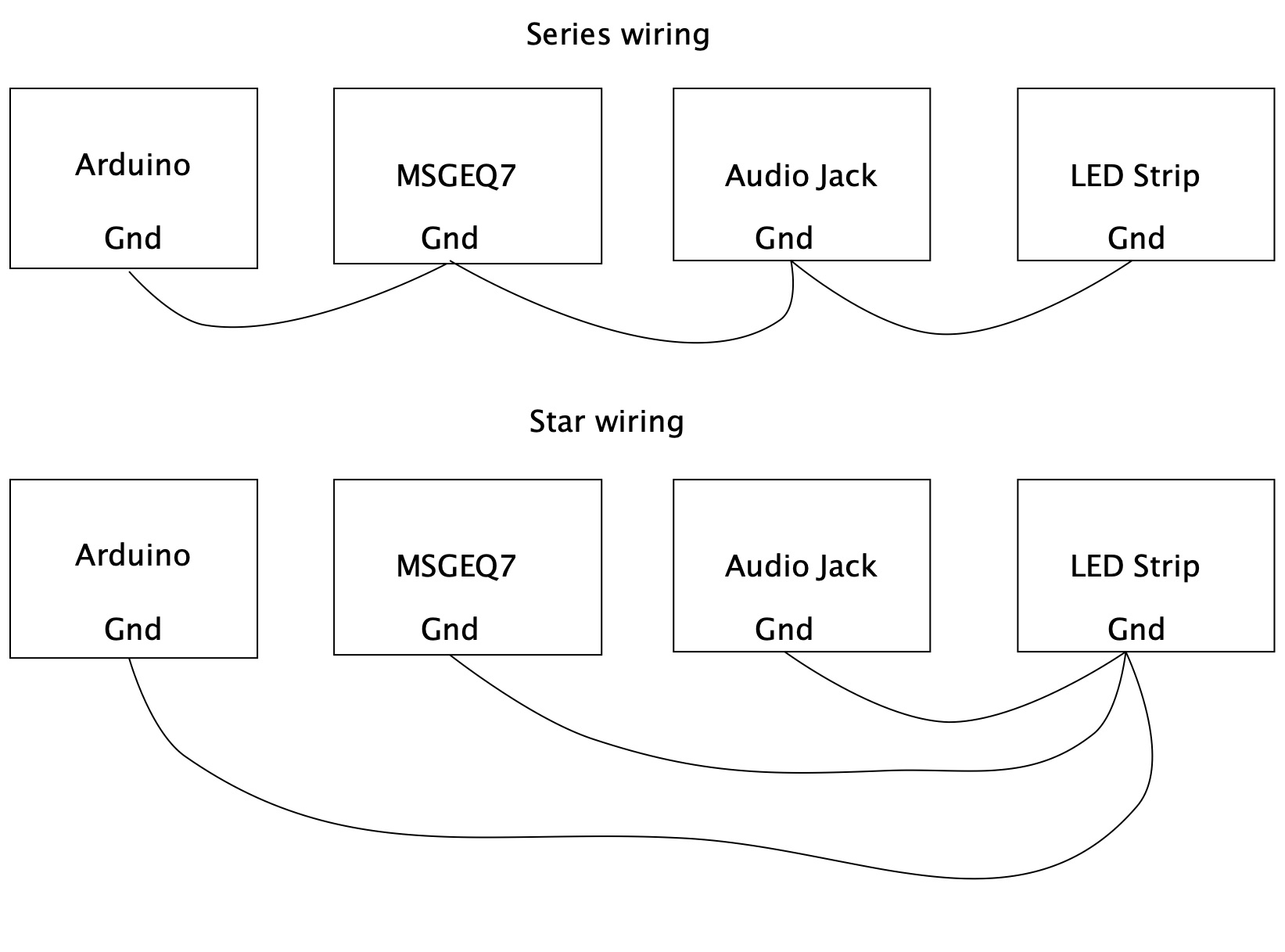
It sounds like the AMP gnd is sharing the motor gnd.
Have you got the AMP gnd connected DIRECTLY to the power supply terminal, and likewise the motor gnd terminal.
Also do the same with the 18V positive wires, go direct to the power supply.
It is called a STAR type connection and isolates each devices current from each other.
If you gnd the AMP input do you still get the fault.
Have you got a 0.1uF capacitor across the motor terminals, as close the the motor as possible?
Keep ALL audio signal wires away from power carrying wires, if low level audio, use shielded cable if the connection is long?
Can you please post a copy of your circuit, in CAD or a picture of a hand drawn circuit in jpg, png?
Hand drawn and photographed is perfectly acceptable.
Please include ALL hardware, component names and pin labels.
Not a Fritzy picture.
I've uploaded my schematics and a reduced version showing where the problem is happening (I think). None of the other components make any difference, if I remove them the problem is still there. The issue is only between the motor and the amp.
For this project I'm working with letterboxes. All of the electronic and mechanical components (and cellphones working as small displays) are inside the letterboxes, so there isn't much room to keep things far from each other... or even have cables. All of it should be working from one single PCB. I have only one cable coming out of the letterbox (hidden in the pole) to the 18v power adaptor. So i'm using a step-down converter to get the 5v for the microcontroller. Some buttons, an I2S module, a potentiometer and a motion sensor take power from the esp32. The amplifier and motor take the power directly from the 18v supply.
As shown in the image (below), the problem is in the ground between the emitter of the mosfet and esp32 (marked with a gray/blue line). I think it's creating a kind of ground loop. If I remove that line, the amp works fine, but the mosfet can't be controlled (so no motor). The funny thing is that, even if the motor is not connected, I still get the problem, so it has nothing to do with inductance (and yes I have a capacitor across the motor). I have both the motor's and amp's gnd connected directly to the 18v supply. I believe the Input GND is already grounded inside the Is2 module.
I've read about the star (and delta) connections but I'm still not sure how I could implement it in this design.
I've tried powering the microcontroller with a 5v supply and keeping the 18v just for the motor and amp, but as soon as that ground line gets connected I get the same problem. I think it would work if I had two 18v supplies, one just for the amp, and the other one using the step-down converter to power the motor and esp32. However, I don't want to go that way because each adapter is about $20 and i'm building 16 (maybe 20) of these letterboxes. I'm already over $600 of my original budget and people are starting to raise their eyebrows (mainly my wife) and I still have other things planned. I'm hoping to not exceed my budget by more than $1000 usd.
Maybe your previous message had the solution and I didn't get it, would you be kind to help me see it. Or if you see something different by looking at the schematics, could you drop me another line?
I would suggest that this is your problem. You need some heavy decoupling between the power and the motor and again between the power and the amplifier.
I would use two Pi filters for this. A Pi filter is the last one on this page about decoupling. http://www.thebox.myzen.co.uk/Tutorial/De-coupling.html
Also I would put a 0.1uF ceramic capacitor across the motor, as close to the motor as possible. I would also use star wiring to connect the grounds.
This sort of problem is difficult to cure because any motor will generate noise and any high gain amplifier will pickup signals because they have a high input impedance. The other thing you can do is to reduce the impedance of your amplifier by putting a resistor between input and ground. Unfortunately this will also reduce the signal going into the amplifier and it will not be as loud. So you have to experiment with the resistor value for the best compromise, start off with a 4K7 resistor, make it smaller for less noise, or bigger for more volume.
Thanks for your advice. I will buy the appropriate components to try what you suggest on Monday. I, however, suspect it might not solve the problem since (as I mentioned in my last message) I get the problem even if the motor is not connected, I mean, having everything else shown on my second image (including mosfet and diode for the motor) but not the motor. I'm mostly intrigued by the star wiring that @TomGeorge had also suggested but I'm not sure how I would implement it without having the necessary "double ground" to drive the motor. I'll reflect on it.