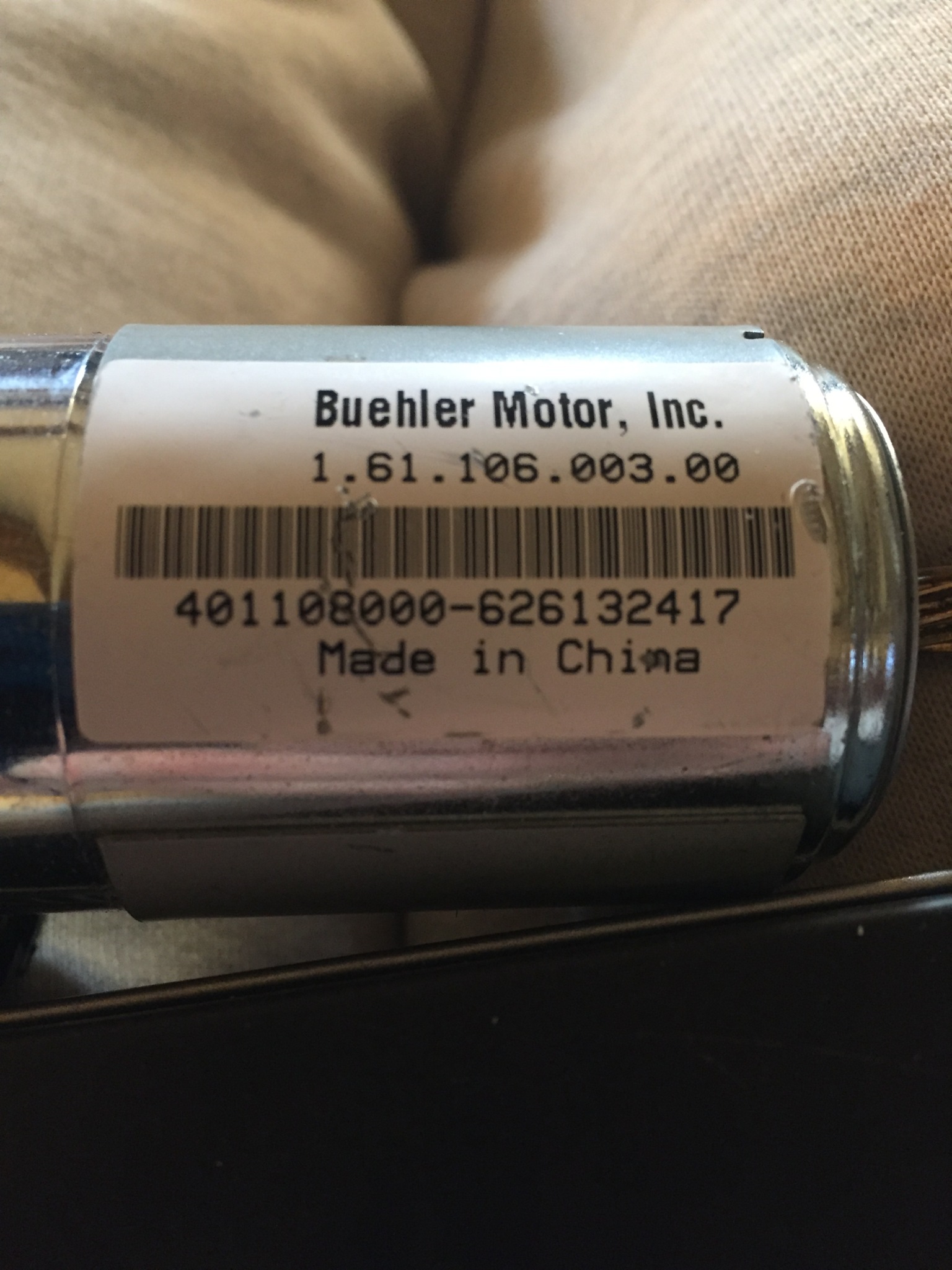
I recently was able to rescue a fairly nice Buehler 1.61.106.003.00 DC motor from the scrap heap. I have several Buehler motors and they seem to be of pretty high quality. Unfortunately I have been unsuccessful in finding any information about this one. I believe its a 24 Volt motor, but can't verify that. I plan on contacting Buehler today to see if they can shed some light on it. I think this came from a Xerox machine, at least the ones I have found with Google were all used for that purpose.
Normally I would just hook up a power source and see what happened, but this particular motor has a speed sensor attached and I would really like to experiment with it to try and build a closed loop dc motor speed controller. I don't have any use for one right now, but it gives me another opportunity to experiment with Arduino.
What I am wondering is if there is any way to determine the pin outs for this sensor. Here are some photos of the sensor and motor. I am pretty sure the far right two pins are for dc power, but I don't want to just put 24V across this and blow the sensor.
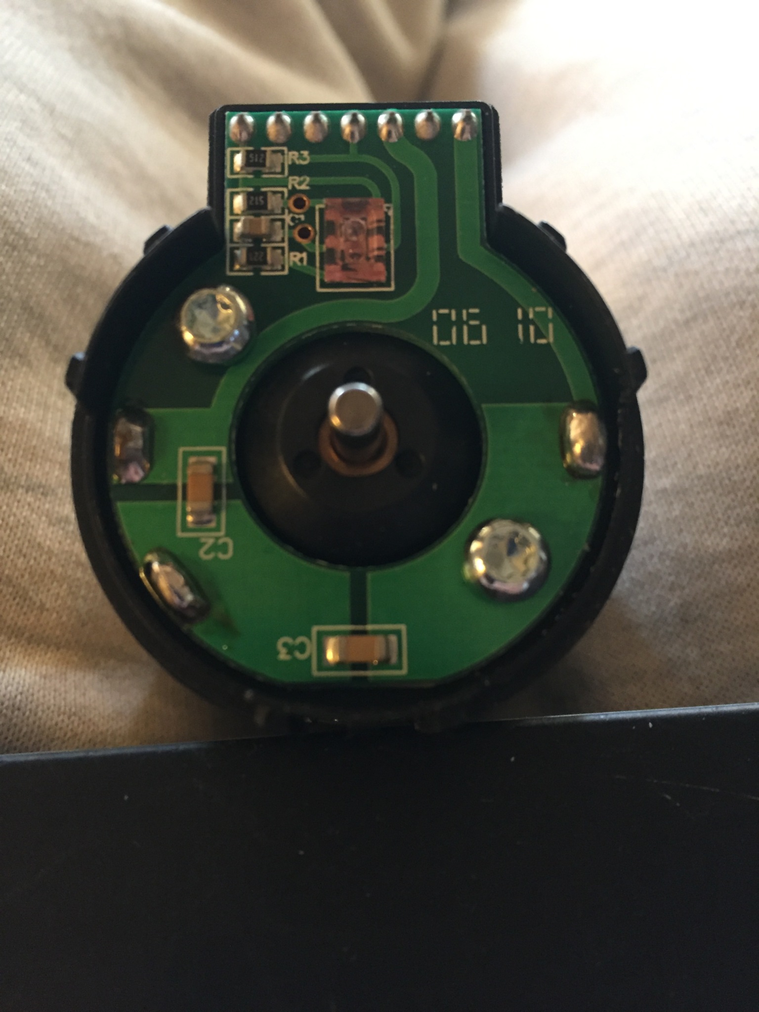
From just studying the circuit board, it appears the far right pins 1 and 3 are power for the motor. I am curious about the function of the two Capacitors labeled C2 and C3. Pins 4 and 7 may be the sensor outputs, but I am not sure. I am also curious where the sensor gets it power from as well. Unless that is what the large section of printed circuit is for at the lower left. If anyone has any ideas on how determint the connections of this sensor, I would be very appreciative.
Thanks for any help or suggestions.
Ok,
So here's my plan. First try to trace the pins to the circuit board to determine the pin outs, especially the power. Then use 12V power and first see if the motor runs. 12V should not harm the sensor. Then test pin voltages to ensure that when I hook them to the Arduino I don't fry the board. Then hook everything up and power the motor. That way I can figure out what the output is. Then I will have to figure a way to manually count the shaft rotations for a few minutes to figure the number of pulses per minute. Once I have that number I can program the Arduino to measure the rpm.
Should be a fun project.
Assumption for power to the motor appears correct.
2 capacitors marked C2 and C3 are RF suppression.
One of each connect to each brush connection with their common end connecting to the motor case.
As for the encoder connections, more detail of the opposite side of the board and it's connections would be required.
Having said that, it is normal for a capacitor ( marked as C1) to be placed across the encoder supply.
While it might be acceptable to provide a 12v dc test supply to the motor, it is advised NOT to do so with the encoder.
These normally run at 5v logic level and 12v could most likely destroy the whole thing.
Once again these are normally an open collector configuration (whether magnetic hall sensor or ir optic) with the resistors shown to properly bias the device underside. Output could even be a dual sensor for direction detection.(quadrature)
I would be checking with a multimeter (set to low ohm) first to see that none of the encoder terminals connect to the motor supply.
Details of the underside connections would be able to be traced out and a circuit of connections would possibly give an insight as to what lies beneath without the need to remove the pcb.
There are a couple of vias shown ( pcb circular holes) which continue the circuit underside.
bluejets:
Assumption for power to the motor appears correct.
2 capacitors marked C2 and C3 are RF suppression.
One of each connect to each brush connection with their common end connecting to the motor case.
As for the encoder connections, more detail of the opposite side of the board and it's connections would be required.
Having said that, it is normal for a capacitor ( marked as C1) to be placed across the encoder supply.
While it might be acceptable to provide a 12v dc test supply to the motor, it is advised NOT to do so with the encoder.
These normally run at 5v logic level and 12v could most likely destroy the whole thing.
Once again these are normally an open collector configuration (whether magnetic hall sensor or ir optic) with the resistors shown to properly bias the device underside. Output could even be a dual sensor for direction detection.(quadrature)
I would be checking with a multimeter (set to low ohm) first to see that none of the encoder terminals connect to the motor supply.
Details of the underside connections would be able to be traced out and a circuit of connections would possibly give an insight as to what lies beneath without the need to remove the pcb.
There are a couple of vias shown ( pcb circular holes) which continue the circuit underside.
I picked up another motor today, so I have two now. I will take one and de-solder the board from the motor for further study. I have read several articles on finding the outputs and what they are connect to, and everything I read said exactly what you have told me. I will take some readings tomorrow and draw a circuit diagram of what I find. Hopefully that will help determine how to wire thing us.
Many thanks for the input. Pictures tomorrow.
Hi,
Please read the forum instructions and post your images into your posts.
Tom...

TomGeorge:
Hi,
Please read the forum instructions and post your images into your posts.
Tom...
Tom,
Thank you, I was concerned with loosing detail. But it seems I was needlessly worried.
bluejets:
Assumption for power to the motor appears correct.
2 capacitors marked C2 and C3 are RF suppression.
One of each connect to each brush connection with their common end connecting to the motor case.
Didn't understand this at first, so did some research. If i understand how capacitors work, they block DC current but charge to a certain voltage level and keep that level until discharged. So I think what they do primarily is to keep the DC current constant and smooth out any fluctuations in the voltage so the motor will run smoother and with a more consistent rpm.
Is that all about right?
Is that all about right?
Not really. The caps, in this case, shunt higher frequency switching noise from the brushes in the motor to ground, keeping the noise from the power supply.
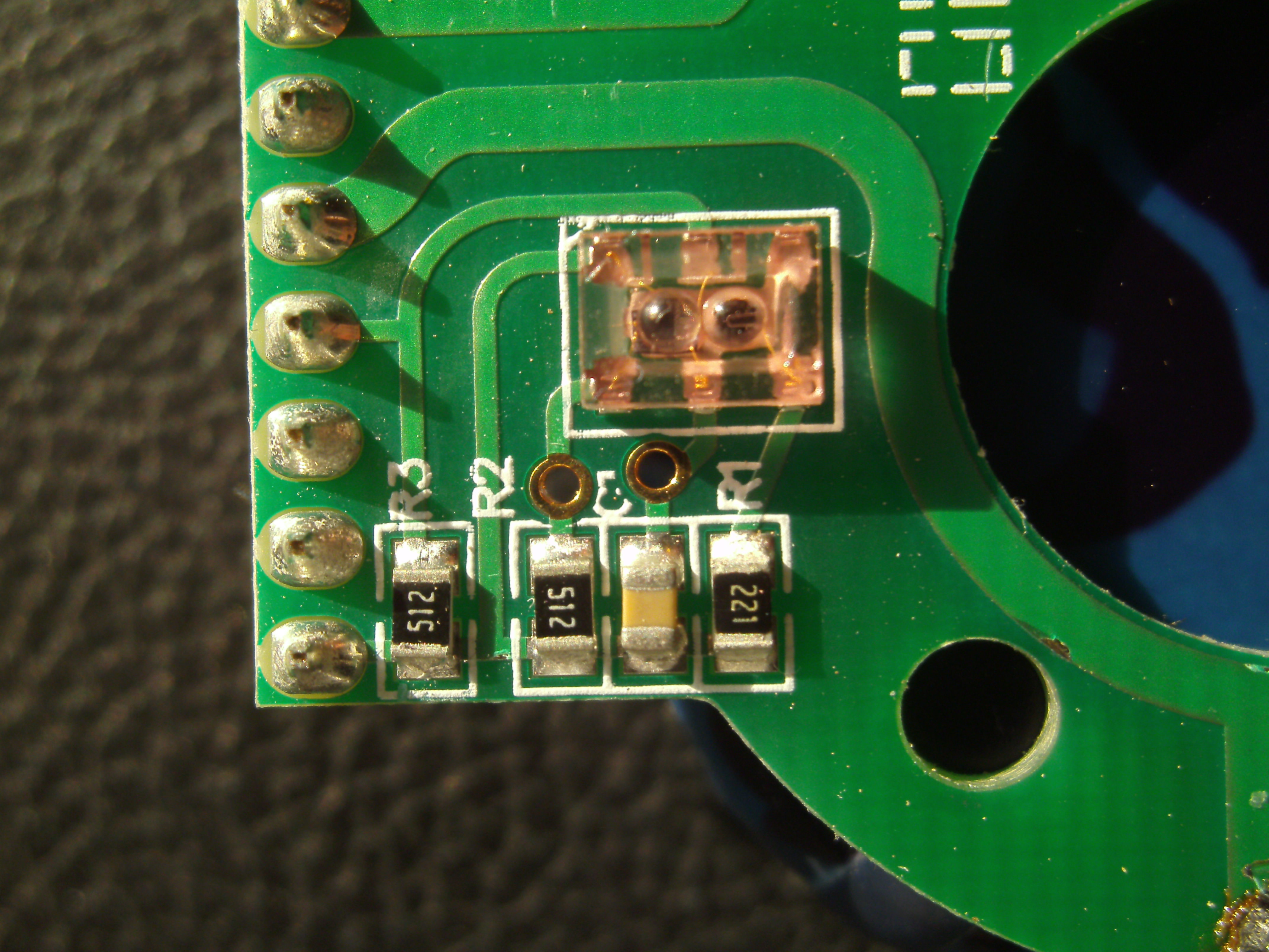
Spent last evening taking Macro photos of the board after I de-soldered it. Based on the pictures I took and doing a continuity test of all the pins, I created the attached drawing. I found what I think is the optical (sensor or pretty close to it) that gave me some concept of the pin outs. If my assumptions are correct, namely the sensor is pretty close to what is on the motor, and my continuity testing was accurate, I think I now have a pretty good idea how to wire things up. Based on the spec sheet I found the max voltage should be 5.5 V. But I think I'll start with 3 and go up from there.
My first test will be to see if I can bet the led emitter to light up. If its an led and not an ir led I should be able to see it. Then I can go forward and start hooking things up to arduino and see what happens.
Here's a photo of the board after I removed it from the motor.
One interesting thing, the spec sheet which is also attached, says to use a 220 resistor, pretty close to the 220 resister on the board.
sensor.pdf (38.9 KB)
av02-0088en.pdf (162 KB)
Ok, now you have the light source and the light sensor out and identified. Where is the part attached to the motor that interrupts or reflects the light from the light source so the sensor knows the motor has moved.
Paul
Paul_KD7HB:
Ok, now you have the light source and the light sensor out and identified. Where is the part attached to the motor that interrupts or reflects the light from the light source so the sensor knows the motor has moved.
Paul
Paul,
Pretty sure it all in one module. The light pink module in the center of the board. From what I have read and seen, the emitter and detector are in the same module. If you look at the attached sensor.pdf file it is the schematic I have made based on my investigation. Notice the module in the center has the emitter and detector all in one. When attached to the motor there is a disk on top of the board attached to the motor shaft that has about 500 lines on it. That should be the actual device that allows the sensor to determine velocity.
Yes, that is the device I was asking about. And as there only one sensor, it can only register movement and not direction of movement.
Is the disk slotted or is the disk transparent with printed black lines?
Paul
Sensor drawing pin 6 has resistor shorted out.
With two 512 resistors and only one 221, I would be inclined to think that there are two detectors and one emitter.
That being the case then a quadrature sensor.
Starting from the bottom of the photo and say bottom terminal is pin 1, then pin would be 5v supply as it is common to both 512 resistors.
Other side of R3 goes to pin 4, so say it is (A) output.
All resistors are common to the 5v supply so other side of R1 is the emitter LED.
Logic would have it that the via on R2 goes to pin 2
This is why I asked for you to meter the connections but didn't happen.
You need to check this...............
If above correct, then pin 2 is (B) output.
Further assuming the via on the capacitor goes to pin 3, then this is ground.
Only thing is there is also a 5V feed to the clear plastic section( trace between 2*501) which could be for a schmitt trigger.
Paul_KD7HB:
Yes, that is the device I was asking about. And as there only one sensor, it can only register movement and not direction of movement.
Is the disk slotted or is the disk transparent with printed black lines?
Paul
Disk is clear with printed black lines. Yes pretty sure it is only used for movement. I think it was removed from a xerox machine so direction was probably not too important for that purpose.
bluejets:
Sensor drawing pin 6 has resistor shorted out.
With two 512 resistors and only one 221, I would be inclined to think that there are two detectors and one emitter.
That being the case then a quadrature sensor.
Starting from the bottom of the photo and say bottom terminal is pin 1, then pin would be 5v supply as it is common to both 512 resistors.
Other side of R3 goes to pin 4, so say it is (A) output.
All resistors are common to the 5v supply so other side of R1 is the emitter LED.
Logic would have it that the via on R2 goes to pin 2
This is why I asked for you to meter the connections but didn't happen.
You need to check this...............
If above correct, then pin 2 is (B) output.
Further assuming the via on the capacitor goes to pin 3, then this is ground.
Only thing is there is also a 5V feed to the clear plastic section( trace between 2*501) which could be for a schmitt trigger.
When you say "meter the connections" I assume you mean to test resistance from the pin on the far left to the pin on the sensor itself. Problem is there is no way to access the connections on the sensor module. The back of the PCB is clear with no connections except the interface (7 pins on the left). I think all the components are pad soldered to the PCB and the sensor is covering all the pads.
I am an absolute novice when it comes to electronics. I enjoy working and making things do what I want but if someone were to ask me to design a circuit, I would be completely lost. I am also pretty limited with what I have to work with. About all I have is an old Fluke multimeter, so pretty limited.
For example, I was unable to measure the resistence of the resistors on the board. I don't know why, but kept getting zero reading.
I really appreciate all the help I have gotten from this forum.
I'll keep plugging away and eventually I may have a better understanding of electronics, but right now its a really fun hobby that lets me combine computers and electronics together to build things I can use in other things I am building.
No, meter the connection from each of the vias to the output connection row.
We can see where the via connects at the photo but not where the other end goes underneath.
Assuming they both connect to the output pins.
To get zero readings on the resistors, you probably have the meter set to too high a value.
What is the meter and what settings....?
Show where you are placing the meter probes.
512 would have a value of 5,100 ohm so above the standard low ohm range on the multimeter.
This would need to be set on 20K range.
Whereas the 221 is 220 ohm and would need to be set on the 2000 range.
This is dependant on your meter scales.
bluejets:
No, meter the connection from each of the vias to the output connection row.
We can see where the via connects at the photo but not where the other end goes underneath.
Assuming they both connect to the output pins.
To get zero readings on the resistors, you probably have the meter set to too high a value.
What is the meter and what settings....?
Show where you are placing the meter probes.
512 would have a value of 5,100 ohm so above the standard low ohm range on the multimeter.
This would need to be set on 20K range.
Whereas the 221 is 220 ohm and would need to be set on the 2000 range.
This is dependant on your meter scales.
Ok, I set my meter to 200 ohms (lowest setting) and tested each via. I checked all the pins even the motor connectors and did not get any reading except on the pin each via is connected to. I then checked the "downstream" side of the resistors and capacitor, again no reading. I did get readings when I had the meter set to sound. This setting is also the setting I use to check leds. Very strange. So I am beginning to wonder if the board may be shot?
I can see the runs on the bottom of the board to the vias but nothing else.
I had the meter set to sound to test continuity. Then to 200 to test the resistors. I was testing on the soldered connections on each end as best I could. My meter says 1 when open and it never changed when I tested across the resistors. I was not able to get any reading from any of the resistors?
The connections are pretty small and my probes are pretty large. I need to find a better set of leads I think for this kind of small work.
1... Show the meter
2... Test from each via...to each output pin ....draw result
3... Meter on continuity will measure nothing except a low resistance path....forget it and use low ohm (200) for continuity and correct range for measuring resistance.
4... Good luck..
except on the pin each via is connected to.
Might seem unimportant to you but I for one would like to know........ which pin is that..?? Gees.... :o
This is what I have so far...

bluejets:
1... Show the meter
2... Test from each via...to each output pin ....draw result
3... Meter on continuity will measure nothing except a low resistance path....forget it and use low ohm (200) for continuity and correct range for measuring resistance.
4... Good luck..
except on the pin each via is connected to.
Might seem unimportant to you but I for one would like to know........ which pin is that..?? Gees.... :o
Ok,
Here is the picture of my multi-meter. My fluke is in my other shop, this is a HF Centech that I have had for a while and works pretty good.
I checked from each VIA to each pin at the 200 ohm setting. All showed open connections. I will try it again tomorrow.