I have noticed that all modern printers use DC motors with optical encoders on the shafts. They seem to be allot fast, quieter and accurate compared to steppers. I was wandering how hard it would be to build you own optical encoder that you can put on a dc motor?
Basically Following this idea:
I cant imagine it is two hard?
You have a counter and then every time the disk turns it will make the light flash and for every flash you add one to your counter? So you could almost make a "stepper" with a dc motor.
I was just wandering if anyone has done this? Not buying some expensive encoder kit, but building their own one?
I would appreciate any comments or thoughts on the idea.
If you want to detect direction as well as amount of movement, you need to use 2 photo interrupter instead of just one. The code track can just be a series of holes drilled in the disc at regular intervals, with the hole diameter about half of the distance between hole centres or slightly greater. The 2 photo interrupters can both read the same holes, they just need to be placed so that one of them is over the centre of a hole when the other is over the edge of a hole.
I've been wondering about this concept also. How does one ensure the motor stops at a specific hole, and stays there?
I've been wondering about having a worm gear reduction from the motor to the shaft with the encoder. That should solve the problem of ensuring things stay in one place, but there is still the problem of getting the motor to stop at a specific hole.
Robin2:
I've been wondering about this concept also. How does one ensure the motor stops at a specific hole, and stays there?
If you know where the motor started from, you can count the number of holes you passed. Typically, you would have another sensor to tell you that the motor or whatever it is driving is in the "home" position.
DC motors with encoders in printers wheter they are for paperfeed or the movement of the head are parked on thier holding position by shorting the motor wires. This way the motor stays locked as soon as the encoder feels movement there is a correction in the opposite direction the movement is applied from the outside. Further there are special algorithms inside the firmware of the printer that control speed and accelaration for the position calculation. The encoder position is used for refrence to get to the required position with higher accuracy. DC Motors move for and backwards.
Paperfeed encoders work with 300 LPI. Head movement encoders are 150 LPI.
It's not much use knowing where the motor has stopped if it has stopped at the wrong place and you have ruined something because of that.
Whether printers use stepper motors or encoded DC motors they are extremely precise, but perhaps the printer manufacturers have decided that it's cheaper to spend money on complex software (which costs nothing to reproduce) in order to reduce the costs of hardware when they make hundreds of thousands of devices.
I'm not sure if the people who have commented about printers mean that controlling a DC motor is easy or difficult - perhaps they can clarify?
I've been thinking some more about this. It would be very convenient for a project I'm thinking of as an alternative to stepper motors mainly because it would be easier and cheaper to connect DC motors if it didn't matter about slippage between the motor and the driven shaft (because the encoder would be on the driven shaft). Also I have a few DC motors gathering dust (which is the equivalent of money burning a hole in your pocket ). I also have model-aircraft electronic speed controller which can be driven from a single Arduino pin - it doesn't do reverse, but that may not matter for testing the concept.
I am hoping that if the load on the motor provides friction the motor will stop quickly (instantly?) when the power is removed and won't be able to freewheel past the desired stopping point. And it should be possible for the Arduino to command the motor to run fast for (say) 60 steps and then do the last 10 slowly so it doesn't overrun the end point. The tricky bit may be moving a single step if there is significant starting torque/inertia to be overcome. But maybe that could be achieved by backing off 10 steps and moving forward 11.
As I have enough stuff it should be easy to test.
I'm also wondering if an encoder could be made by marking black and white stripes on a piece of paper wrapped round a wheel. The beauty of such a system is that the stripes could easily be printed with a computer and you could easily try out different numbers of steps.
My thought was motor control is an engineering design, specific to the application and the resources available.
as the poster above highlights , in printers, which are zero profit machines, ever cent counts, and software is cheap. so we put more effort into the algorithms to control the motors, and know in detail the environment they are in, loads etc.
there is no point putting a 10 dollar motor in a product that sells for 50 dollars, in the tens of thousands.
BUT
for some products that sell one or two a year, and no two customers are 100 the same,and at a much higher cost, we do use much more expensive motors and controllers.
so yes, one can use a opto encoder as indicated to replace a stepper motor, but not always, and some times its just not worth the effort.
Initial tests with a cheap DC motor (controlled by PWM from an Arduino) and some Lego gears suggests there is a speed at which the output shaft will stop instantly when power is removed provided there is a resistive load on the shaft so it can't freewheel (I have a slightly stretched rubber band over the shaft).
The next step (deliberate pun) is to build a simple optical encoder and see can the Arduino keep track of where the wheel is and get it to stop at a specific point.
If this works (and it probably should) it would mean that any motor could easily be used in an application where one would usually think of using a stepper motor. Having written the software once it could easily be reused.
Robin2:
Initial tests with a cheap DC motor (controlled by PWM from an Arduino) and some Lego gears suggests there is a speed at which the output shaft will stop instantly when power is removed provided there is a resistive load on the shaft so it can't freewheel (I have a slightly stretched rubber band over the shaft).
If you short the motor terminals together immediately after removing power, this has a braking effect on DC motors and usually slows them down very quickly. Most H-bridges can short the load.
Thanks for that. It's been in the back of my mind but I haven't got as far as trying a hbridge yet and I'm have no experience yet (from any other projects) of how effective it might be.
I've been thinking more about this. I don't think there would be any problem making a DC motor controllable with feedback from an encoder. However I can't think of any simple way to coordinate the movement/position of 2 or 3 motors so that each moves only in strict proportion to the others. It's no good if motor A gets to the end of its run while motor B is only half way there. The problem (as I see it) is that the speed of the DC motors can only be determined after the event whereas with a stepper motor (provided it is operated within its proper envelope) the speed can be predicted precisely.
So, unless someone has a bright idea for coordinating DC motors I'm not doing any more with this.
Hi All,
Don't you just have say 20 holes around the disk or GEAR and start counting as soon as the motors start moving, then you know 20 pulses is one rev of the wheel, it could be more or less depending where the holes are?? and gear ratio, etc. BUT once you know it's OK and constant. A slotted opto switch is what you need for this, or you can just use an IR-LED and IR-phototransistor.
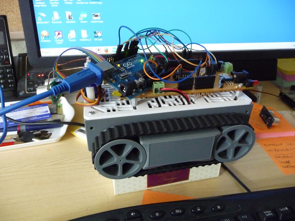
Here's a picture of my current Buggy-Bot this only has one hole in a gear that does 4 revs to one rev of the driving wheels, not that useful!! OK 2 pictures, the first when it was being controlled by a Picaxe, but I am a very new convert to Arduino, and finding C a bit of a struggle, pic 2 my Uno taking control.
What happens if one motor runs slower (perhaps has a heavier load) and has only got to hole 16 when the other is at hole 20 but you NEED both motors always to be at the same hole?
I haven't been able to think of a way to solve this problem - especially if you want the motors to run quickly for several revolutions - say 1000 "holes".