Hi,
I am trying to measure the time of the flight of sound waves between two accelerometers when one of them is hit. So I plugged my sensors on a tree trunk leaving 20 cm distance between them. I know that the tree trunk is healthy (no decay, hollow, or crack) and according to previous studies after the first sensor is triggered, sound waves should reach to second accelerometer in 200-250 us. The problem here is that I obtain results between 32-500.
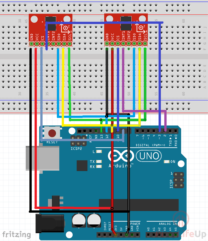
I am using adxl345 accelerometers using SPI communication and Arduino Uno R3 as master. How can i read values more precisely?
The code and the schema are given below.
#include <SparkFun_ADXL345.h>         // SparkFun ADXL345 Library

ADXL345 adxl1 = ADXL345(10);
ADXL345 adxl2 = ADXL345(9);

int interruptPin1 = 2;
int interruptPin2 = 3;

unsigned long time1[10];
unsigned long time2[10];

int counter1;
int counter2;

void ADXL1_ISR();
void ADXL2_ISR();

void attachInterrupts();
void detachInterrupts();

void setModule(ADXL345 adxl);

void setup(){
  Serial.begin(9600);

  setModule(adxl1);
  setModule(adxl2);

  attachInterrupts();
}


void loop(){
  if (counter1 > 2 && counter2 > 2) {
    detachInterrupts();
    if(time1[0] > time2[0]){
      Serial.println(time1[0]-time2[0]);
    }
    delay(1000);
    attachInterrupts();
    counter1 = 0;
    counter2 = 0;
  }
}

void setModule(ADXL345 adxl) {
  adxl.powerOn();                     // Power on the ADXL345
  adxl.setRangeSetting(16);           // Give the range settings // Accepted values are 2g, 4g, 8g or 16g // Higher Values = Wider Measurement Range
                                      // Lower Values = Greater Sensitivity
  adxl.setSpiBit(0);                  // Configure the device to be in 4 wire SPI mode when set to '0' or 3 wire SPI mode when set to 1
                                      // Default: Set to 1 // SPI pins on the ATMega328: 11, 12 and 13 as reference in SPI Library
  //adxl.setFullResBit(1);
  adxl.setActivityXYZ(1, 1, 1);       // Set to activate movement detection in the axes "adxl.setActivityXYZ(X, Y, Z);" (1 == ON, 0 == OFF)
  adxl.setActivityThreshold(10);      // 62.5mg per increment   // Set activity   // Inactivity thresholds (0-255)

  // Setting all interupts to take place on INT1 pin
  adxl.setImportantInterruptMapping(2, 2, 2, 1, 2);     .

  // Turn on Interrupts for each mode (1 == ON, 0 == OFF)
  adxl.InactivityINT(0);
  adxl.ActivityINT(1);
  adxl.FreeFallINT(0);
  adxl.doubleTapINT(0);
  adxl.singleTapINT(0);
}

void ADXL1_ISR() {
  byte interrupts = adxl1.getInterruptSource();
  time1[counter1] = micros();
  counter1++;
}

void ADXL2_ISR() {
  byte interrupts = adxl2.getInterruptSource();
  time2[counter2] = micros();
  counter2++;
}

void attachInterrupts() {
  attachInterrupt(digitalPinToInterrupt(interruptPin1), ADXL1_ISR, RISING);   // Attach Interrupt
  attachInterrupt(digitalPinToInterrupt(interruptPin2), ADXL2_ISR, RISING);   // Attach Interrupt
}

void detachInterrupts() {
  detachInterrupt(digitalPinToInterrupt(interruptPin1));   // Detach Interrupt
  detachInterrupt(digitalPinToInterrupt(interruptPin2));   // Detach Interrupt
}
PS: I have used an array for storing time because when I tap on a accelerometer, it generates multiple interrupts (probably because of the echos). The first index in the array gives us the first trigger time.