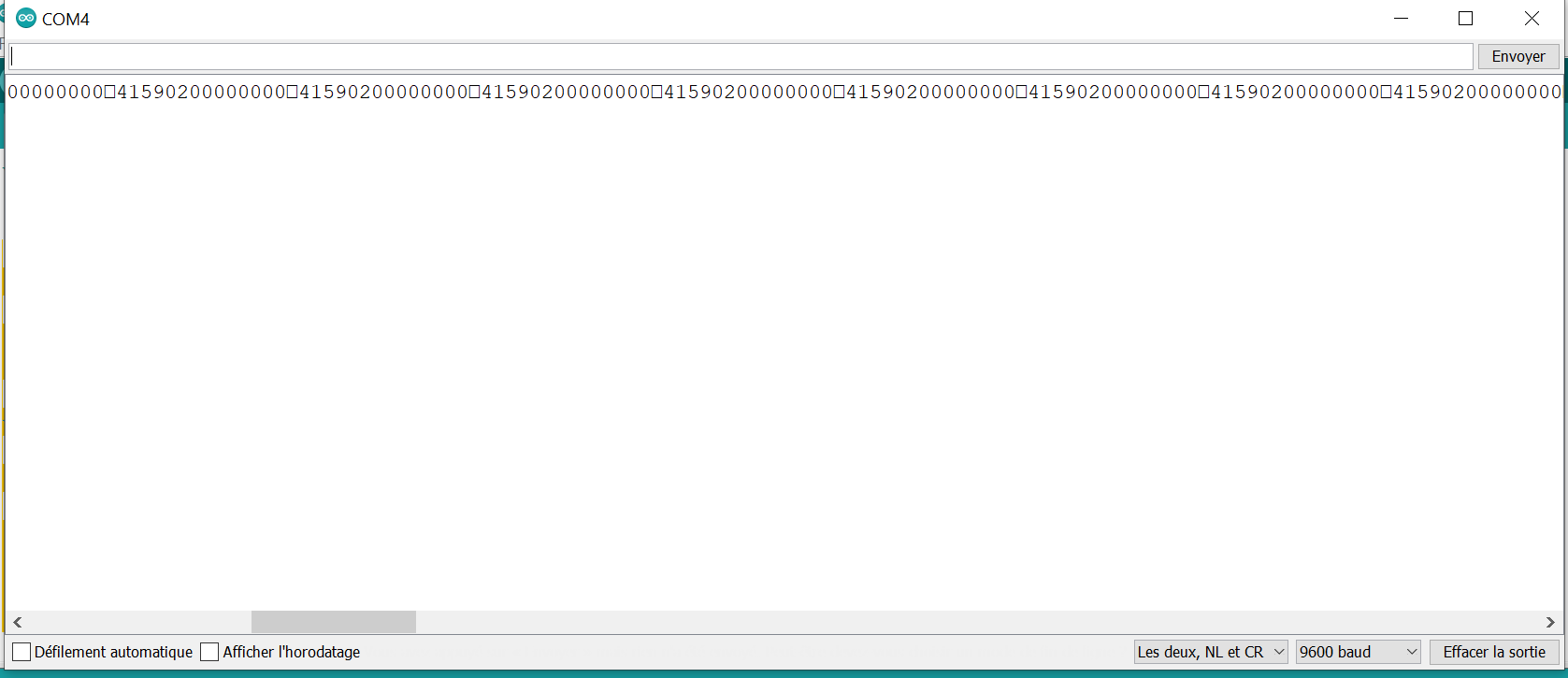
I need to retrieve the important data from each stream, and first I would like to detect the start of each stream.
As you can see from the screenshot, a square appears at the start. But how can I detect this ?
Here is the code I'm using :
void setup() {

  // initialize both serial ports:

  Serial.begin(9600);

  Serial1.begin(9600);
}

void loop() {

  // read from port 1, send to port 0:

  if (Serial1.available()) {
    int inByte = Serial1.read();
    Serial.write(inByte);
  }
}
Please post the complete sketch that reads and prints the data. See How to get the best out of this forum for advice on using code tags. Please copy the Serial output and paste it here on code tags along with an example of what is being sent by the unnamed device
I would guess that you are using Serial.print() to print the data. If so, have you tried using Serial.write() instead ?
As mentionned in the device 's datasheet, there are both start and end word on D15 and D0, but I guess they are non printable characters,.
I don't know what to do to make them visible and detect them, and then manage to decode the entire stream from D15 to D0 and retrieve my valuable data.
I might need to fill a buffer when I detect a StartWorld, but how to detecd that specific byte (D15) ?
You don't need to print them to detect them. Read a byte, test it's value, if it is the start or end then do something else print (or write) the byte
However, the datasheet mentions an RS232 interface. How are you doing teh conversion between RS232 on the device and TTL on the Arduino and which Arduino are you using ?
Ok, I don't need to print them but how can I detect ? What is the value of a Start or End ? Is it a 1 and a 4 in the ASCII table as HEX value ?
No, it seems to be 02 and 0D instead ! Thanks @GoForSmoke.
The ASCII codes below 32 are control codes and can't sensibly be printed. The ASCII code of 32 is a space, so the line of code detects whether the current byte is a control character and if so prints its value in HEX
If the Start byte is being printed as 02 then that is its HEX value. You can test it using its HEX value like this if (inByte == 0x02)
or in decimal if (inByte == 2)
Have a look at this tutorial on serial input basics - Example 3 (reply #2) seems to be what you need. You will need to set startMarker and endMarker to match your datastream - i.e. set them to 0x02 and 0x0D.
/*

  Multiple Serial test

  Receives from the main serial port, sends to the others.

  Receives from serial port 1, sends to the main serial (Serial 0).

  This example works only with boards with more than one serial like Arduino Mega, Due, Zero etc.

  The circuit:

  - any serial device attached to Serial port 1

  - Serial Monitor open on Serial port 0

  created 30 Dec 2008

  modified 20 May 2012

  by Tom Igoe & Jed Roach

  modified 27 Nov 2015

  by Arturo Guadalupi

  This example code is in the public domain.

*/

//Déclaration fonctions :
void send_message();

void setup() {

  // initialize both serial ports:
  Serial.begin(9600);
  Serial1.begin(9600);
}

void loop() {

  // read from port 1, send to port 0:
  char buf[17];

  if (Serial1.available()) {
    int inByte = Serial1.read();
    static int n = 0;
    if (inByte == 2) {
      n = 15;
      Serial.println("START WORLD received");
    }
    if (inByte == 13) {
      Serial.println("\nEND WORLD received\n");
    }
    buf[n] = inByte;
    n -= 1;

    if (n == 0) {
         for (int i = 14; i >= 0; i--){
        Serial.write(buf[i]);
        }
    }
  }
}
I now need to extract and get the data in shape to make it easily human readable.
How could I concatenate byte D1 to D8, change the result to int, then apply the byte D9 (decimal point) and D10 (polarity) ?
I may be wrong here but it looks like the received data is going to be stored backwards in buf - i.e. the first received byte is stored in buf[15].
If you were to reverse the process and store the received bytes starting in buf[0], then you could overwrite the characters received that represent D14 to D9 with the ASCII code for zero (0x30 or 48 dec) and providing the contents of buf end with a NULL, then one of the string handling functions could extract the value for you - maybe atoi()?
I think you should then convert the value to a float and divide it by 10, 100 or 1000 depending on the value of D9. Don't fotget the sign bit in D10.
EDIT: I think you can get the atoi() function to start with the char at D8 so you don't overwrite the location of the decimal point, the sign or the units.
Here is the piece of code I ended with at the moment :
/*

  Receives from serial port 1, sends to the main serial (Serial 0).

  This example works only with boards with more than one serial like Arduino Mega, Due, Zero etc.

  The circuit:

  - any serial device attached to Serial port 1

  - Serial Monitor open on Serial port 0

  created 30 Dec 2008

  modified 20 May 2012

  by Tom Igoe & Jed Roach

  modified 27 Nov 2015

  by Arturo Guadalupi

  modified 15 Jull 2021

  by me to meet my needs about PCE-FM200

  This example code is in the public domain.
  This code is intended to send a PWM signal on pin13 depending on the received value from PCE-FM200's RS232 port
*/
#define ouputPin 13

void setup() {
  // initialize both serial ports:
  Serial.begin(9600);
  Serial1.begin(9600);
}

void loop() {

  // read from port 1, send to port 0:
  char buf[17];

  if (Serial1.available()) {
    int inByte = Serial1.read();
    static int n = 0;
    if (inByte == 2) {  //Start of Text = DEC2
      n = 15;
      Serial.println("START WORLD received");
    }
    if (inByte == 13) { //Carriage Return = DEC13
      Serial.println("\nEND WORLD received\n");
    }
    buf[n] = inByte;
    n -= 1;

    if (n == 0) {
      int value = (buf[1]) - 48 + (buf[2] - 48) * 10 + (buf[3] - 48) * 100 +  (buf[4] - 48) * 1000 + (buf[5] - 48) * 10000 + (buf[6] - 48) * 100000 +  (buf[7] - 48) * 1000000 +  (buf[8] - 48) * 10000000;
      Serial.println(value);
      float val = value / pow(10, (buf[9] - 48)); //adjust in accordance with the Decimal Point.
      if (buf[10] == 48 + 1) {
        val = -val; // Adjust in accordance to polarity.
      }
      Serial.println(val);

      float Voutput = map(val, 0, 100, 0, 255);  //output a 0-5V signal on pin 13
      analogWrite (ouputPin, Voutput);

      //print complete data stream for check and debug
      for (int i = 14; i >= 0; i--) {
        Serial.write(buf[i]);
      }
    }
  }
}
The generated PWM output signal of course, doesn't take négative value into consideration.
This setup is meant to output a 0-5V signal to a datalogger
Thanks to all for helping and figure out a solution.