hi,
i am trying to decode a signal with a unknown binary information, but i wrote a code to decode it but the code is not working properly. it prints 1 and 0s endlessly.
i have attached a photo of that signal and drive link to the saleac logic session file for you to understand my problems.
in the signal above the first is the start bit which consists 3, 1s.
next the signal between the long 5.04ms pulse and 4.60ms pulse are the information i want to decode in binary format.
Here is the code which i wrote to decode it .
#define receive_pin 2
int first_delay = 418;
int second_delay = 838;

void setup() {
  // put your setup code here, to run once:
  pinMode(receive_pin, INPUT_PULLUP);
  Serial.begin(9600);
}

void loop() {
  // put your main code here, to run repeatedly:
  uint32_t received_byte = receive_data(200);
  Serial.print(received_byte,BIN);
  Serial.println();
}

uint32_t receive_data(int no_bits) {
  while (digitalRead(receive_pin) == HIGH) {
    //wait til the signal goes from high to low
  }

  delayMicroseconds(first_delay);

  uint32_t received_data = 0;

  for (int i = 0; i < no_bits; i++) {
    delayMicroseconds(second_delay);
    received_data |= (digitalRead(receive_pin) << i);
  }
  return received_data;
}
what i need is that, is a idea how can i program ardunio to decode the data as 1 and 0.
and thank you for the response in advance
allen_coelho
Have you tried the different protocols available to you on that analyzer? To me it looks like the output of a PID controller but I am only guessing as I do not have a clue as to what the hardware is.
That makes it very difficult, it can be anything from a sync signal to a lot of information. From the waveform it looks to be very repetitive probably a sync but just a guess. The ST8 is a member of a family of processors, making this even more difficult. Can you post a schematic of the circuit and what it is in? Also which member of the family we are talking about.
Sorry, but your code looking a complete nonsense for me...
In the function receive_data you storing a no_bits number of received bits to the variable of uint32_t type:
but in the main code you calling this function with no_bits parameter as much as 200:
What do you expect to get by writing 200 bits into a variable that is only 32 bits long?
looks like the stream is HIGH when idle, the start bit will be LOW
stop bits will be HIGH guaranteeing that the LOW start bit can be recognized if sent immediately after the preceding data byte
knowing the baud rate, the code should wait 1.5 bit periods after detecting the start bit to sample the first bit in the middle of the bit
all subsequent bits are sampled by waiting 1.0 bit periods
RS-232 Signaling indicates that the the LSB is transmitted first and the the value of the start bit is the value of a high data bit (the data is inverted
if you bit period is 418 (2392 bps ??), then the first_delay should be 627 and the second_delay should be 418 and bits should be inverted
as a test attempted to generate a signal similar to the analyser
transmitting bytes 10101010 11000010 10100101 at 1800baud with a 3mSec delay between bytes I get
isn't he doing something similar to what you are doing ... using an oscilloscope to monitor the output of a UART? this can be the output using Serial.write() or Serial.print()
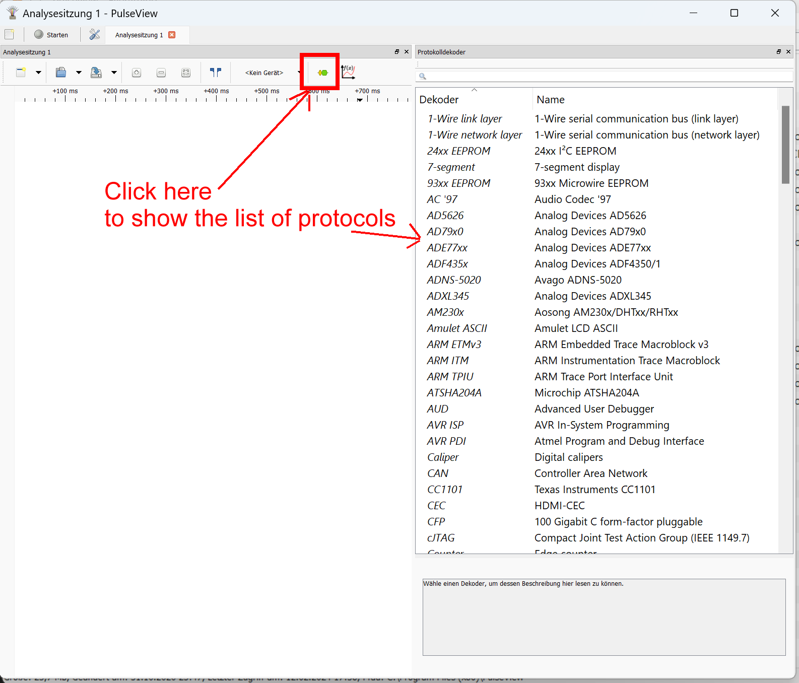
What software did you use to record the signal?
Was it pulseView ?
or
Something else?
I guess PulseView is compatible with Salae because pulseview mentions salae as a usable recording device
This is how I see it: They probably started with Serial/UART at 9600 baud. They probably use software to send and receive the data. Perhaps there are interrupts that take some time, so they had to lower the baudrate to 2400 to make it work.
PulseView has a decoder called "UART", set the Baud rate to 2400 and it should read data.
On the Arduino Uno, a SoftwareSerial port should be able to read the data.