westfw:
I found it very frustrating to try to use fritzing to draw "nice" schematics; it was FAR too difficult to "neaten" a rough diagram... There are similar problems with many generic "drawing" packages; when you attach signals to a part on a schematic, you want there to be an actual "attachment" that isn't changed simply by moving the art and/or the wires...
It can be done with a proper 2D CAD package but it's much easier using a dedicated schematic package. I tend to use the schematics part of LTSpice but that's just personal preference.
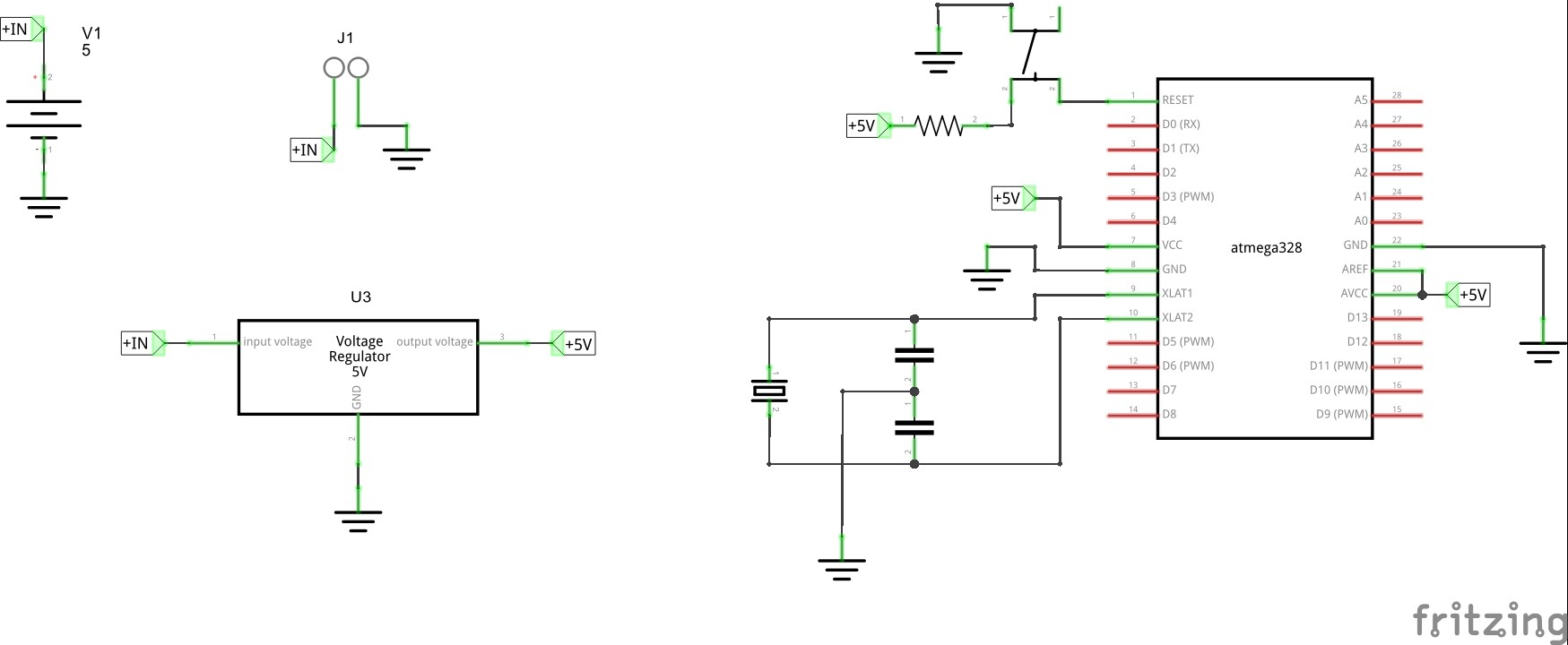
it's great to have all the advise coming in. i have attached a small schematic i have done. would this be considered ok? have i used too many or to few Net Labels etc?
Not bad and you've definitely used appropriate net labels.
I would tend to combine all of the power supply (input jack, capacitor and regulator) into one block instead of using net labels.
The ground symbol on the left of the '328 is really clogging things up and pushing other wires around. Drag it down below the chip (the ground wire will cross under the other connections) and then rearrange 5V and the other wires to come in straighter.
The switch at the top looks like a representation of the common 4-wire tactile switch. In schematics you don't usually show all 4 wires - just the two logical pins. Having 5V flow "across" the switch looks odd.