I'd like to detect current in a cable by wrapping a wire round it connected to the analogue input pin on an arduino uno.
The cable will have 240v AC at anywhere between 0 and 10A. My question is, how many times do i need to wrap the wire round the cable? If i just put a diode on the cable, could i detect the variation?
I only need to know if there is current running through the cable, I don't need any precision.
What is the minimum current you want to detect?
That's going to determine how many windings you need. You'll anyway have to add some extra hardware to detect the minimum, without getting burned by the maximum.
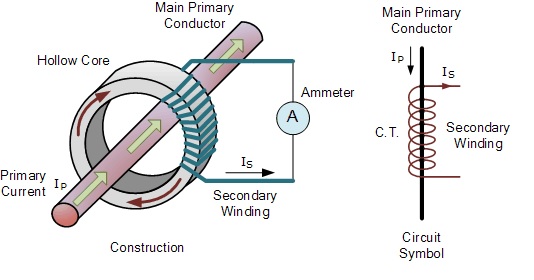
Wire wrapped around a cable cannot be used to measure current flow, because the magnetic field lines are parallel to the wire. For AC current, you can use a "current transformer" (a toroidal transformer), with a single conductor passing through the core, or use a Hall sensor for AC or DC.
Smollett:
I don't mind if it only detects from 5A up...
Use you digital VOM on the AC volt scale and measure the AC volts on your coil with 10 turns around the cable. The meter will show some voltage number when the current is flowing in the cable. That voltage value will tell you if you need more turns or fewer. Could not be easier.
jremington:
Wire wrapped around a cable cannot be used to measure current flow, because the magnetic field lines are parallel to the wire.
Although you are correct in saying that OP's setup will not work, magnetic field lines circulate around a line current - not run parallel. If they ran parallel, OP's setup would work.
OP, you should also take care that you only wrap the current sensing system around the supply wire ONLY and leave the return wire outside - else you will get close to 0A no matter what.
Well, that kills my suggestion, hole is only 0.1 inch. You are aware that only 1 conductor goes through the CT, not all wires in a multi conductor cable.
Although you are correct in saying that OP's setup will not work, magnetic field lines circulate around a line current - not run parallel. If they ran parallel, OP's setup would work.
Which is exactly why I wrote "wire" (for current sense wire) rather than "cable", as written in the OP. Evidently my attempt to avoid confusion failed. Indeed, the magnetic field lines due to the cable current run parallel to sense wire, so if the field lines change, cannot induce a voltage in the sense wire.
Thank you for posting the nice diagram illustrating my point!