I am trying to develop a low cost measuring system with Time - Domain - Reflectometry to measure water level.
I have created the sensor, however i have a problem creating the necessary signal conditioning circuit.
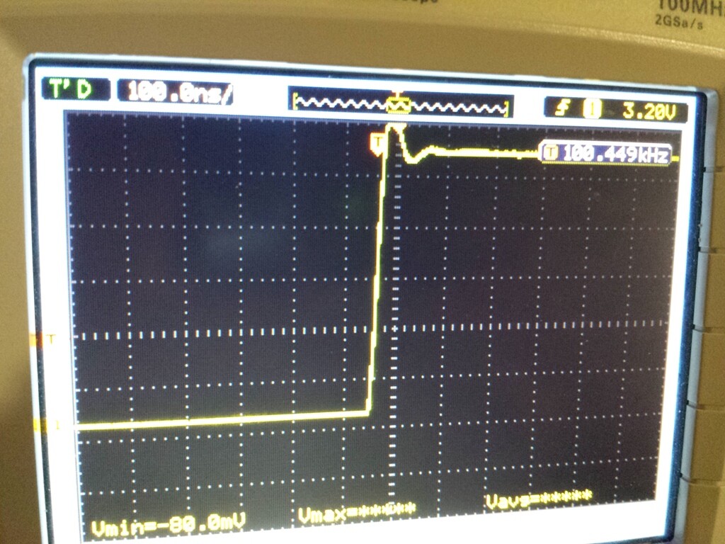
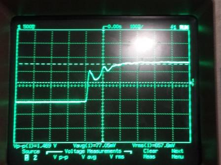
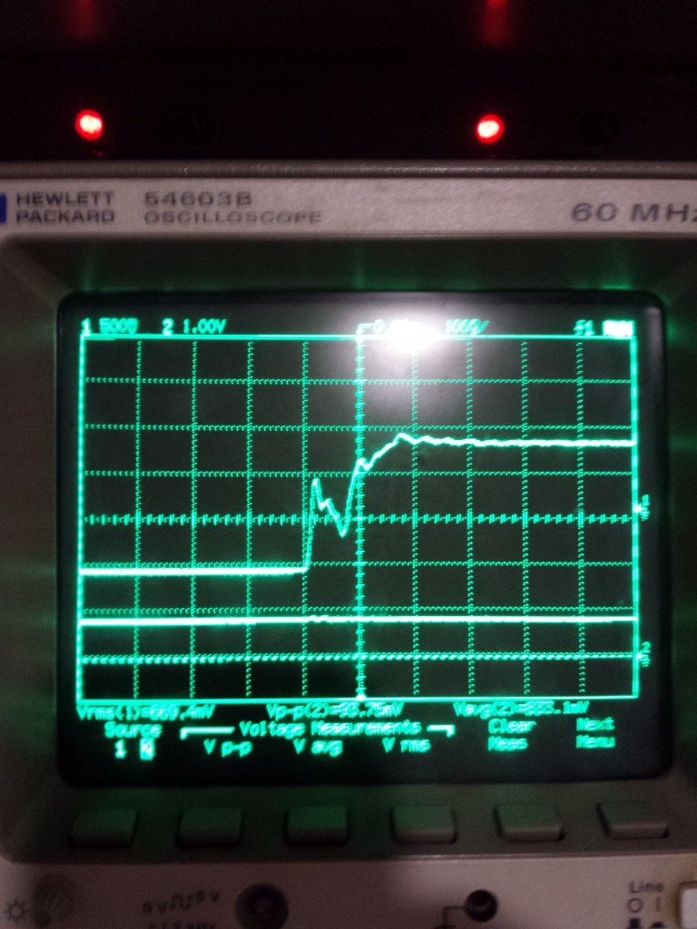
Right now i use the oscilloscope to measure the the changes that occur with the sensor, i zoom in the pulse and measure the changes in Vp-p and Vrms . The best thing is to measure the pulse lenght. The changes are on the length of the pulse in series with how deep the other sensor is in the water.
The last image(the yellow one) is the rising edge without the sensor.
The other two are with the sensor in different water levels.
It is not entirely clear to me what you are describing but a very robust way to measure pulse width is to use a comparator Comparator - Wikipedia to perform the signal conditioning. Input the signal that you inputted to the o-scope into a comparator with and adjustable threshold. Connect the output of the comparator to one of the interrupts of the Arduino, initially set the interrupt to trigger on a rising pulse. The routine (ISR) that is called when the first interrupt is triggered, clears the interrupt, zeroes the clock, delays long enough so the signal is in the nice smooth region, and sets up the interrupt to be triggered on a falling pulse. When the second interrupt is triggered the ISR will read the clock and this is the pulse width, then turn on the interrupt for the rising pulse to be ready for the next pulse.
Just see this post and maybe worth looking at this. I use a dual comparator and a GP22 timing chip and measure the time difference between the steps. The comparators are adjustable using digital potentiometers.
I read the thread several times, i was very very excited about your results, however i really can not get how the comparators provide you with this measurement,
this is why i thought of another way to measure the signal.
i read the changes, that occur with cable length.
Just reminder that i am looking to measure the water level, not cable faults.
Another note i want to add is that my goal is to create a standalone system to read with the arduino for level measurements.
lomanas123:
I read the thread several times, i was very very excited about your results, however i really can not get how the comparators provide you with this measurement,
Look at this image
and you see the first step is the pulse starting to travelling down the cable and the second step is the reflection coming back from the other end of the cable. If you adjust the comparators so one is triggered by the first rising edge of the signal being sent and the other to trigger on the rising edge of the reflection you can time the difference between the pulse being sent and the reflection coming back. If you know the cable velocity you can then work out how long the cable is.