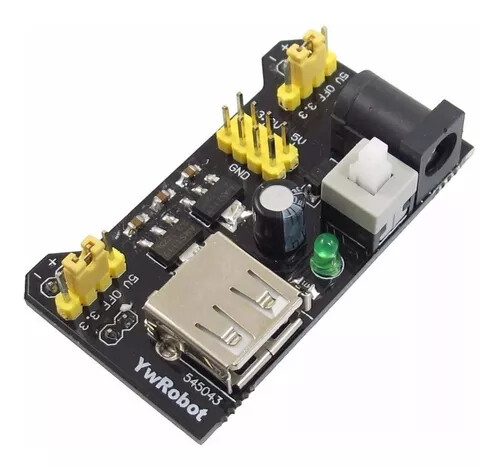
When I power my Uno using a 9V supply, the DHT11 I'm using works fine, reporting both Temperature and Humidity. When I use the breadboard power supply that came with my starter kit I get a read error from the DHT11.
Anyone know what might be causing this and what I could do to fix it please?
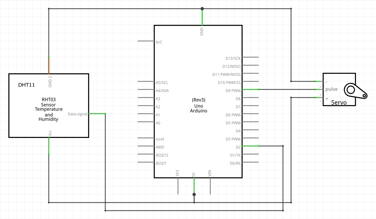
I haven't got a schematic but the sensor is just a 5V, A ground and a control wire from Pin 2. Then I've got a servo on Pin 9 to indicate temperature. If I put the 9V plug into the Uno then no problems. If I put the power supply on the breadboard and put the 9V into the power supply, then I get a read error on the Serial Monitor.
I've attached a photo of the set up, it's quite a simple set up. When I put the power supply onto the breadboard the wiring doesn't change.
The breadboard has gaps in the power rails but I have them bridged. And the sensor supply is from the power supply side anyway.
Perhaps I'll get a volt meter on the power supply output. I'm calibrating the servo position at the moment. The nearest numbers in the photo are servo angle, the other numbers are °C.
I'll be using a Nano and the 9V supply soldered onto a veroboard once I get the thing finished so it's not too much of a problem but I would prefer to use the breadboard power supply while I'm testing it all. I thought perhaps this was a symptom someone might recognise!
Thanks for the information. I've read your link and I've downloaded Autodesk_EAGLE. I'll knock something up. I've also downloaded Fritzing from AndriodErode but that might be limited as it's a free version.
If so, make sure the jumpers are correct set up to 5V;
make sure you don´t have broken jumpers. Breadboard power supply GND and Uno GND might be interconnected.
Additional hint:
In the schematic you´re powering the sensor and the servo through the Arduino 5V pin, it can work, but it´s not recommended. Motors (and servos) should have a separated power supply. If your final configuration will have a +5V rail provided by the breadboard power supply, connect the servo to it, not to the +5V of the Nano.
I do mean that one, yes. And I've used it for a while on other setups without problems so I'm sure the jumpers are ok.
The schematic is showing how it is. The 9V supply is plugged into the Uno and the 5V on the Uno supplies the positive rail on the breadboard. I could try plugging the 9V supply into the breadboard power supply to feed the servo and connecting the DHT11 to the Uno 5V. The sensor would then be powered from the USB, would that be ok?
I suppose it doesn't. But it is a schematic! Do I get a break for it being my first schematic?
I'll have a look to see if I can find the library items to show the configuration of the 9V power supply plugged directly into the Uno and the Uno 5V Pin wired to the breadboard power rail.
Where would you show the 9V connected to the Uno on the schematic?
If the wiring doesn´t change, Uno +5V and the breadboard power supply +5V are connected together on the same rail.
The final version of your project will be connected to the PC?
If the final version of your project will not be connected to the PC, the Nano can get its power from the same +5V rail provided by the breadboard power supply, just as the DHT11 and the servo. You´ll be using the breadboard power supply as a DC-DC converter to get 9V down to 5V. In this case you´ll not use Nano Vin (because Nano Vin is connected to the Nano regulator, the voltage will drop and it won´t work at all).
Perfect illustration of the absolute need for one. Because, I have no idea where you have connected it, or want to connect it.
The purpose of the diagram is not mysterious. It is simple to show, in a clear and unambiguous way, how things are connected.
In the time you spend defending your incomplete diagram, you could have completed it and posted it. Actually, we still need it. So please do.
It's perfectly natural for a beginner to omit things. But that doesn't mean they should continue to do so, forever. I'm not trying to make you feel bad, I'm just trying to get the information that we need to help you, out in the forum where people can see it.
Please see FernandoGarcia's reply above. It's a perfect illustration of the absolute need to answer a question in a clear and unambiguous way. Seems to me it would not have been possible for me to spend time improving my poor schematic without first coming here to find out how! You didn't make me feel bad, don't worry. I'll do the schematic again and post back.
Thank you for the positive reflection on this forum. I see how one thing led to another. Indeed it is quite rich in resources for this field of interest. Also it gathers a lot of things in one place, that are spread somewhat thinly on the internet.
I once was solely responsible for a small telecom office, the rule was - if you change any part of the equipment, you must change the drawings (in a cabinet). If you change any part of the drawings, the equipment has to follow suit.
The penalty for not following this was not only management ire, but the disgust of your peers. The policy really sped up troubleshooting and installations.
Likewise, I can't find an image for a breadboard mounted PSU with the 9V plugged into it and 5V into the breadboard positive and negative rails, so I did this:
Doing the breadboard drawing made me realise that I had forgotten to link the Uno GND to the breadboard negative rail! The link is in now and everything is working lovely!
Big thanks to everyone that helped. I would like to produce correct schematics for my project, of which this is part. What would be the convention for showing, or where would I find an image for a breadboard PSU?
A module like that is usually shown as a box, with all the inputs and outputs labelled the same as they are on the module (or functionally if they aren't labelled). Same really, as the way you've shown the DHT module.
Realize, you are not showing wires, but connections.
An image of a breadboard would be completely inappropriate to be included in a schematic.