I noticed that when I turned off the power supply (connected to 9V battery), it still showed a green light. This was coming from the arduino, yet I only had pins 5,4,3,GND , A0 connected on the arduino.
So where is this unwanted power supply coming from?
Would my DC motor also be drawing current from the arduino since there is an unwanted power supply?
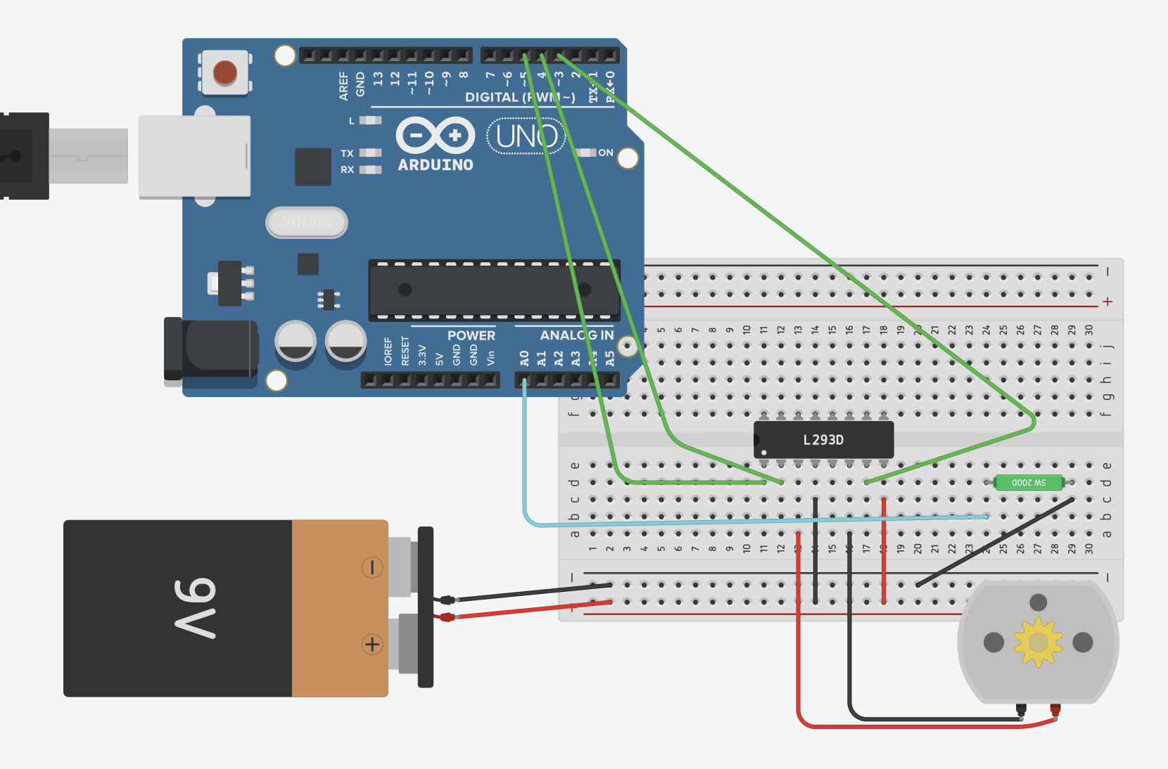
I disconnected it, but it was basically the most common way of connecting: 9V battery + power supply, L293D, DC Motor, Arduino
Schematic of my circuit or almost my circuit. There was a fan connected to the DC motor, and the goal was that when there is tilting (don't overlook the tilt sensor!), the DC motor was supposed to switch off.
Things to note:
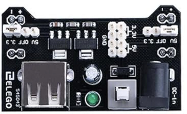
The 9V battery was connected to the power supply module (module from the Elegoo Super Starter Kit). I didn't see the power supply module in TinkerCAD
Pretty sure that I did not have Pin 5 connected to GND and Pin 16 connected to the +ve rail. My circuit worked though.
Questions:
When it tilted, the DC motor was supposed to switch off, however, it did not and rather slowed down. This was fixed when I did a digitalWrite() and set the tilt pin to be HIGH at the start. Can someone explain what the issue was – if it is more than what I saw at the surface level?
So back to the main question, I clicked the button on the power supply module to turn off the supply from the 9V. However, the green light didn't turn off. The only things I remember connecting to the power supply module were: all the GNDs & Pin 8 from the L293D. The L293D supplied a voltage from the arduino?
And another main question, when I ran my arduino code, my DC motor would run slowly. When I turned on the power supply module, it would then work as normal. Where was this power coming from – when the power supply module button was not pressed to be turned on.
===============================================================
Corrections:
I have posted the corrected schematic below:
"SW200D" is supposed to be a tilt sensor, i dont really know what SW200D is
Why is the wire connecting Pin 8 to the +ve power supply of the power module (module not on diagram) causing the power module's green light to turn on? I pressed the button to turn it off.
A sneak path through the data lines. Very, very bad for the continued health of your Arduino. That's all I can surmise in the absence of a very much required schematic.
What were they connected to?
Does the other bit of hardware have it own power supply?
Is most possibly the problem.
Can you please post a copy of your circuit, a picture of a hand drawn circuit in jpg, png?
Hand drawn and photographed is perfectly acceptable.
Please include ALL hardware, power supplies, component names and pin labels.
Can you please post a copy of your circuit, a picture of a hand drawn circuit in jpg, png?
Hand drawn and photographed is perfectly acceptable.
Please include ALL hardware, power supplies, component names and pin labels.
The logic (5volt) supply of the L293 (pin16) is not connected.
What is the SW200D part inline with A0 supposed to do.
Hopefully you're not using a smoke alarm battery.
Leo..
It's basically a switch (datasheet), so it needs to be wired like a switch. Specifically, you'll need a power source and a pull-up or pull-down resistor, and the output should probably go to a digital I/O pin, not A0. Currently, the way the SW-200D is wired, it is doing nothing.
Do you have any code for this project?
I would suggest connecting the SW-200D between GND and a digital I/O pin, and setting the pinMode for that pin to INPUT_PULLUP.
Alternatively, here is an example that uses an external pulldown resistor and a 5-V power source.:
I can;t understand what you've written. The SW-200D is a tilt sensor, I don't have to imagine it. If you're trying to say that you are using a different tilt sensor (not the SW-200D), then in all likelihood, my previous comment still applies. If not, you need to specify exactly what tilt sensor you are actually using.
If you want to get anywhere with your problem, I would suggest that you make some effort to respond to the request that has been made by @TomGeorge (twice) and others in this thread:
Yeah so i have a question (I have the 16-pin L293D)
Pin 8 --> external power supply
Pins 3&4 --> GND
Pin 16 --> 5V from Arduino
Pins 12&13 --> GND (same GND as above)
Do I need to do this if i am using only ONE Dc Motor? Relevant connections on the side that is Pins 1-->8
I understand that pin 16 is for logic, so more concerned about pins 12&13