Did I break the motor, the Uno, the servo, or none of the above?

I don't know how to fix this problem.

The summary line is: is this supposed to happen or did I break my Arduino Uno R3? I tried to power, a small DC motor from my Arduino as the book instructions show, it did not work, but my Arduino still supplies 5 V and 3.3V out, and the LEDs all work.

I am new to Arduino. I am learning it and teaching it to my nine year old son. I was lent a 'Arduino for Dummies' by a friend. Some friends gifted us, the Elego, Uno R3 kit. Both are excellent.

I read through the book, then started using the instructions in a book with the parts of the kit. I am using the snap image of the Arduino on the Ubuntu desktop. The examples in the arduino ide are excellent.

We worked through the LED fade sketche, button sketch, analog input sketch, and serial read and analog in and out sketch. We moved over to DC motors sketch. Following the instructions in the book, I drove a small 3 V DC motor from 5 V on the Arduino. This is demonstrated in the book (see page 148 on the link). I used an appropriate PN222 transistor, resistor and diode. The motor never really turned, but at times it would sing briefly, instead of turning. Since I could not get it to work I turned to the Elegoo website.

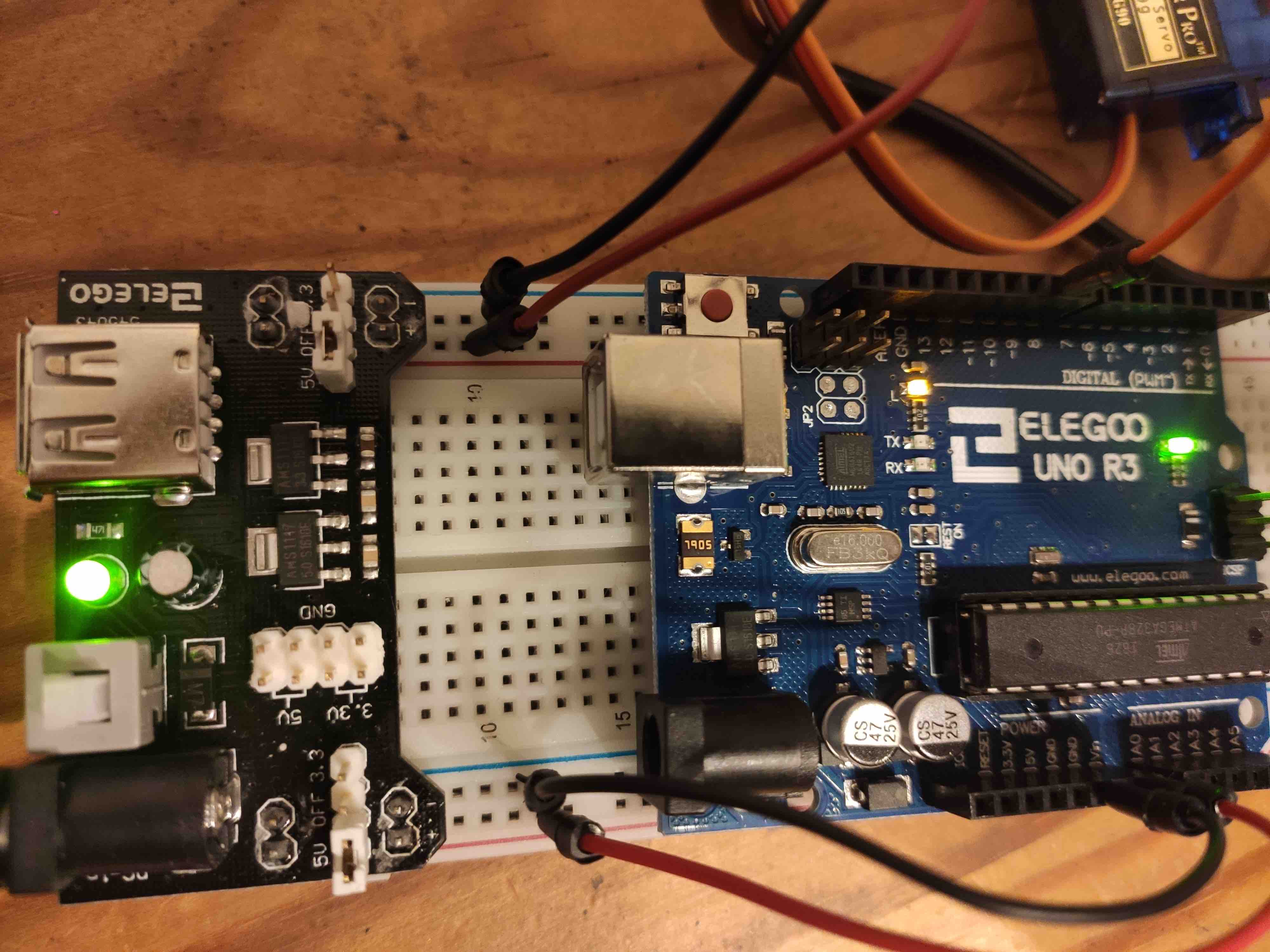
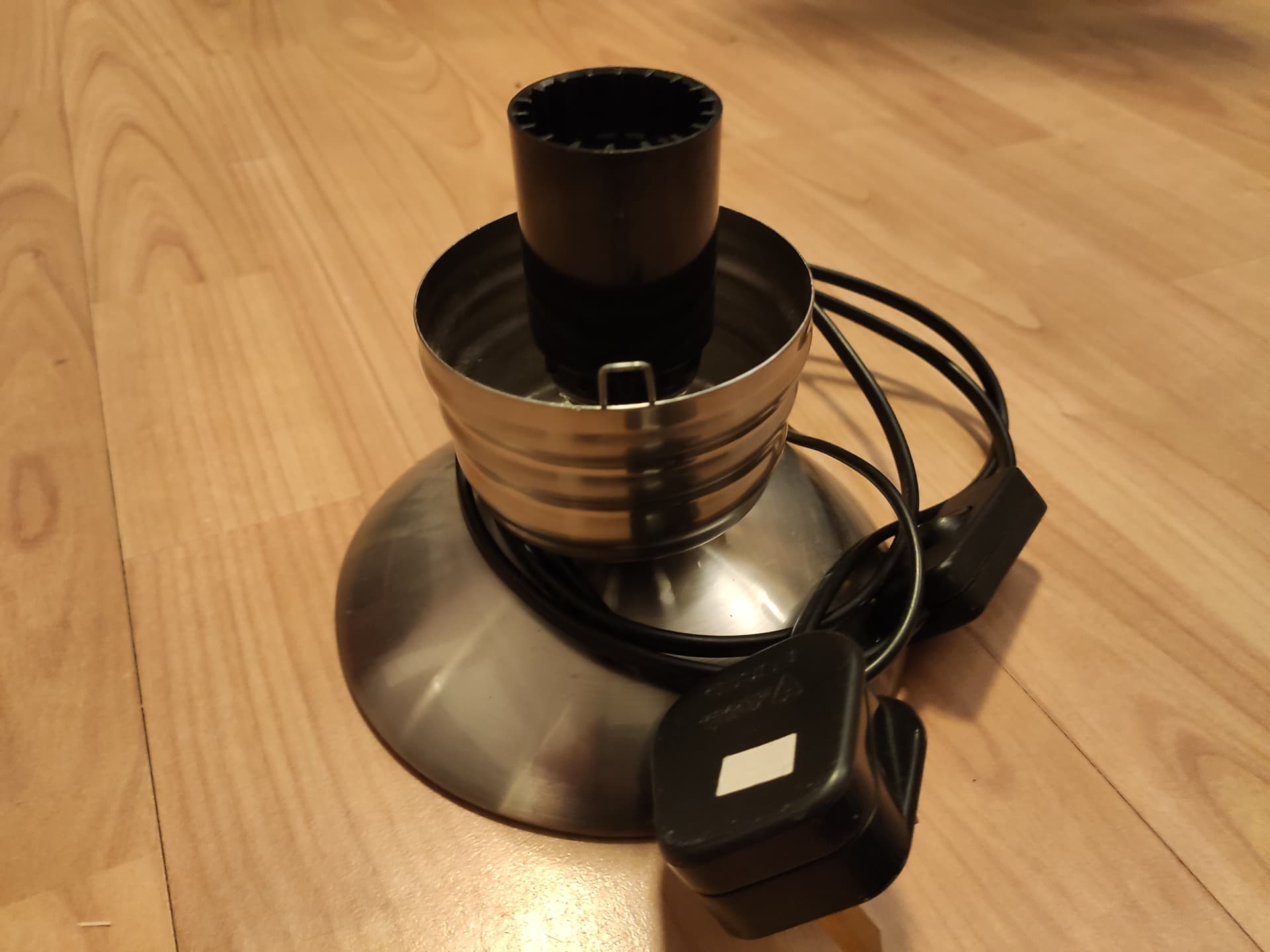
On the Elegoo website, there are comprehensive instructions (and very good too) on how to use the kit, I discovered the lesson (?26) on DC motors and that the motor in the kit requires a power driver. (you can see it in the top left of the image on the link beneath the CD). The Elegoo notes say if used without the power unit you may break the Arduino. So I may have broken the Arduino. I followed the instructions to set up the motor on a DC driver from the Elegoo instructions. The sketch comes from the Elegoo DC driver sketch. With the Elegoo DC driver and the chip suplied, this seems to spin the motor at high speed, medium speed (as the sketch instructs) but at low speed, it would not turn but did sing (from the power unit curiously). It the Motor broken? probably not if it turns. Is it just cheap? maybe.

Going back to the Arduino, I could get the 'broken' motor pin outs to work if I used an LED in place of the motor. This suggests the Arduino is not broken. Equally I could measure voltage across the 5 V outlet of the Arduino. I could also measure 3.3 V across the appropriate Arduino power out terminal. Answering the question is the Arduino broken? I am not convinced.

I moved on in the book to the servo chapter sketch. I connected at as is demonstrated in the book. I uploaded the ide example sketch as the book describes, but no movement, possibly a faint clicking sound. It is clearly trying to do something. I am wondering if this servo is also not able to be driven by the Arduino. However, it was part of the kit by Elegoo and Looking at the Elegoo docs it was wired as Elegoo suggest. Running the sketch makes the Arduino servo click but not move. Is this also just a cheap part? It looks much smaller and cheaper than servos I have seen before.

What do I conclude from this? The Arduino is trying to do something and it should work according to the book and the kit. It doesn't though, but it does do something. I cannot tell if it is broken or not. I am not sure where to go with this problem. The only thing I can imagine is to buy a new Uno R3 out right and test the servo on it. Is this what you do? Or do you have any better suggestions?

Welcome to the forum.

You may conclude that you are doing well. I assume that you have a multimeter ? that's very good :smiley:

Trouble with motors is what almost everyone encounters. It is a normal phase in the learning process. You are right on track :+1:

Background story about power usage:
A 9V battery is not good enough to power a motor and if you use 12V then you might destroy the Arduino board. A small servo motor might need a current peak of 500mA. The 5V pin of the Arduino board can not give that peak. A motor that is rated 1A might ask for a peak current of 10A. When the motor is larger then there are driver modules (or "drivers"). For strong motors, the driver is more expensive than the motor. A similar problem is with ledstrips. Put a ledstrip in your room and you might need a power supply of 20A.

The link to the book did not work for me, this works: https://archive.org/details/pdfy--LpbPxUly33g2cjN
That circuit on page 128 (the 148th page) is okay, although the 5V pin is probably not strong enough for a motor.

Can you show a photo with the power supply and all the wires ? We can help to make a circuit for the motor. Start with the servo motor, that is easier. Do you have a 5V power supply ?

Is that a official snap ? Which version is it ?
I download the linux zip file from here: https://www.arduino.cc/en/software, then I unpack it in folder and make shortcut/link to 'arduino-ide'. I do not run a install script.

1 Like

Sorry for the slow reply. Childcare and the site was unavailable for a bit.

Wow, that's super helpful. Thanks very much for a quick reply and considerate response.

Photos coming shortly.

I tried to download the Linux package three times. Downloads each time, but every time I could not find the install script. All the instructions said run the install script, I looked in every directory. Could not find it, so went to the software store and found the official package snap.

Even unzipping again and downloading now I cannot see the install script in the location where it is supposed to be, even with a sudo ls -al.

Yes I will start with the servo. Posting shortly.

I had trouble with the Linux install. I used this link to get the IDE working on my Mint 20.

Ahh, again super helpful, I was going to do just that, thanks you saved me a headache. For now I am running an old dell with ubuntu for the ide and running the sketch on the R3 Uno. RPi will be when I free one up.

Thanks again.

The link title I posted is misleading... it worked for my 32 bit and 64 bit Linux (I do not have RPi).

I don't care about instructions, I want to keep my system clean :soap:
I unpack the file of version 2.0.3 somewhere in my home folder and I do not install anything. I check with a terminal and run ./arduino-ide. If that works, then I make a shortcut/link to it and put that link on my desktop. That's all.

In my package manager, I have removed everything that might cause trouble (arduino, java, openjdk, jre, modemmanager, brltty).

The modemmanager got in the way in the past, I think that is fixed. Recently my Arduino IDE could not see any Arduino board and that was because brltty was activated. I don't know how that is possible, but I removed it.

Sorry about the delay, I do a run of long shifts.

Okay, so good news. Starting from scratch and plugging together as per the instructions on this link under the servo chapter. It works here is a photo of it.

You asked about the power supply, I checked. It is a wall socket 9V DC 1A adaptor. Using the Elegoo sketch, I can turn to a defined angle. Using the Arduino IDE sketch I can do a gradual sweep. It was doing this when I took the photo.

I think this is all-round success. It demonstrates both the (cheap?) Servo is functional and the Arduino is functional on the pins shown (5v, GND and PWM on pin 9). Next step is the DC motor.

See the next post.

We are all frowning and making faces behind our computer :grimacing:

The voltage regulator on the Uno board has to dissipate the heat from 9V -> 5V and the 5V pin is not good enough to power a servo motor. A good solution would be a 5V adapter to power the servo motor. It is possible to power the Arduino board also with 5V, for example via the USB connector.

Noted. I have a voltage regulator which can supply 5 and 3.3 volts. I thought this was for the motor only.

No damage yet, still works.

If I disconnect the power and leave it on usb it still functions, so usb supply is good enough.

The supply has 2 rails of independent supply. I can set one to 3.3v and one to 5.0v.

I hope the frowns have gone now.

Both rails were on 5.0v. The R3 had one and the servo had the other. It was doing the servo sweep in this sketch. No 'hot' or 'smokey' smells. The 'sweep' code is somewhat step-wise.

Moving onto PWM for the dc motor, I presume I would need some 'power' transistors or FETs? in order to convert the low current PWM signal to an increased power?

There is a chip with this kit called the L293D. The docs say this is a 4 driver something and can control up to 2 dc motors (one 'driver' per pole). The layout indicates I would use this chip as power step up as I describe above.

The L293D is very old, it will work with small 9V or 12V motors, but not so well with 5V motors. It is a H-bridge to apply positive and negative voltage to the motor to turn it both ways and with PWM to control the speed.

Adafruit has the best tutorials: https://learn.adafruit.com/adafruit-arduino-lesson-15-dc-motor-reversing

Are you going to build that circuit ? Why not put it aside and forget about it. It is like making shoes out of cardboard, and meanwhile everyone passes by on smooth running shoes.

Today, the drivers for motors are with mosfets.
Look how beautiful this driver is: https://www.adafruit.com/product/3190
Or this one: https://www.sparkfun.com/products/20679
Or this one: https://www.pololu.com/product/2990

Personally, I'd rather you fried your UNO(cheap learning) than your computer's USB(what good is it then?), and I'd rather you didn't power a motor with either(best, no cost other than a separate 5V power supply).
If I wanted to learn a bunch with an UNO, I'd stick a bunch of buttons and LEDs with resistors on the ins and outs, until I had a bit of programming experience anyway. There is no point in powering the servo or the motor with USB or Arduino 5V output, it's only a matter of time. Yes, they might work now, but they may then not work tomorrow. The design is not that robust.
Yes, buy a driver circuit for the DC motor. Buy a 5V supply for that, and for the servos.

I have all the parts to do it with the L293D, I am only bashing my way through each sketch with my son (and my daughter wants a go now!) So I will go with that for now.

I have a need to control a turnable speed for a crafting project, so will come back to the mosfets next. (Not pottery - more like painting concentric rings - I already have a light wood turntable)

That first link makes the point, 'logic power' and 'motor power' as separate voltage ranges. The key point seems to be a shared ground, so if there is any 'relativism' in the stated outputs on the power supplies, then at least there is some 'harmonisation' in the voltages so I don't blow anything.

Thanks for concerns about damaging the usb. That would be super frustrating.

Yes I take your point about programming. I am much less new to programming. I worked through a (really nice) C++ book about 7 years ago, and so I recognise the syntax. Over the last 2 years I have learned (a fair bit) from some Python courses, sites, books, blogs, podcasts and even a conference. I might try micropython with my daughter, as she is familiar with it already.

Thanks for the links, really really useful.

1 Like

Thank you again for your help.

Servo work well with the sweep and position sketches, if:

  1. using power module (5V) to supply the servo
  2. using power module (5V) on other bank to power uno
  3. signal from uno to servo
    Thankyou problem solved. Son inspired: 'can we make robots now?'

DC motor control, powered alone from the power unit shown above, it spins beautifully on 5V, and readily. Built up that lovely L293D tutorial with the pot analogue input to the uno, and the reversal switch. Powered through the L293D, the motor barely turns. Giving it a nudge with my finger and it slowly turns, gradually a little quicker, but not much.

This is an inherited kit from a nice old neighbour who does pottery but could not get his head around the coding. It looks like it has seen light use. Most items are still in their original packet. Could the L293D be damaged, causing slow movement?

Will be on the musical piezo sketches today! Lots of fun!

The L293D does not use mosfets but transistors. The transistors are inside the L293D in a circuit that makes the voltage drop even worse (as they did back then).

According to the datasheet:

5V - 1.4 - 1.2 = 2.4 V
There is only 2.4V left for the motor when the power supply is 5V. You are lucky that it turns at all.
That is the reason that I wrote that it is for small 9V and 12V motors.

There are simulators for Arduino. One of them is called "Wokwi". In the upper-middle of the screen is the start button and then you can click on the buttons: mini-piano.ino - Wokwi Arduino and ESP32 Simulator
Wokwi can also simulate microPython: New MicroPython on ESP32 Project - Wokwi Simulator

1 Like

The kit says it is a 3V motor. Would that handle 9 to 12V? I honestly have no idea. seems to handle 5V directly ok.

No, it will not handle 9 or 12V. It will make sparks and draw so much current that the L293D will release its magic smoke, and the contacts that push against the rotor will get eaten away.
Kids might want to see what will happen when doing something wrong, but there is also a fire hazard or you could damage the computer.
Suppose you use 12V, and the L293D blows, causing that the 12V to enter your Arduino board and via the USB cable to your computer. It is better to stay on the safe side. Silly experiments that go wrong are done best outside with supervision.

How about ledstrips ? It is not in your kit, but it is really fun.

1 Like

No more magic smoke!

I am in the uk and went for this one:

Looking at the addressable LED strips, they look, interesting. They seem to come in whole meter lengths and be about £25 each. They seem quite chunky, 1/2" by 3/8"? I have googled narrower ones, I have a large bulb (dia 12") and I want to make a mock filament. I don't think I needs multicoloured individually addressable, just all of them powered at the same brightness, and close enough to look like a single filement. Are these unrealistic expectations? I am not sure where to look.

I have a similar issue to this motor issue, but with the LCD2016 unit. Different topic, will search. thankyou all.

Does your LCD display not have a I2C backpack ?
Getting the LCD to work with all those wires is hard. We all have been there. We prefer to use the I2C LCD displays with only 4 wires.

If you give a link to the ledstrip and tell what you want to make, perhaps with a picture, then maybe we can tell if that would work. Please be specific. Do you want, for example, warm white all the same brightness, or RGB all the same color. The individually addressable 5V ledstrips are often easier to use than white ledstrips with a higher voltage.
Ledstrip example: Overview | Kaleidoscope Eyes (Trinket-Powered NeoPixel LED Ring Goggles) | Adafruit Learning System

1 Like

This problem is solved, so I set it to solved. The question was 'have I broken it' and the answer was 'no, you're doing it the hard way, do this instead' which was very helpful.

The LCD problem is a different one entirely, and I have posted it here.

My initial project was, 'work through a book with your son and learn some stuff, maybe get inspired'. Success on both counts. The second there is the curiousity. It has inspired at least 3 things:

  1. A motor speed controller to control the speed of rotating small table for a separate crafting project. Details below.
  2. A LCD or LED readout message (birthday message, Links to the ones I have.)
  3. A lighting arrangement for the crafting project.

One and three are related, two is separate completely.

The crafting project: see the photo. I have a lamp base the design of which is (was) a large light bulb. A family member broke the original glass. In effort to replace it, I think I want a horizontally rotating plate to aid in crafting a plastic replacement. (I have the plate I just need a low force/speed driver). Once replaced, it would be an arduino classic to have some interesting/attractive/decorative arrangement it there. I was thinking of a mock filament, coded to flicker as it might have done in Edison's day. But one thing at a time, I will probably just use a normal bulb for now.

I am thinking I can manage finding some LEDs (problem 3), there are good options, thanks for the suggestions. The motor issue is resolved for now (problem 1). The LCD issue is off topic for a motor problem so I started a new thread. I will post a photo over there shortly.