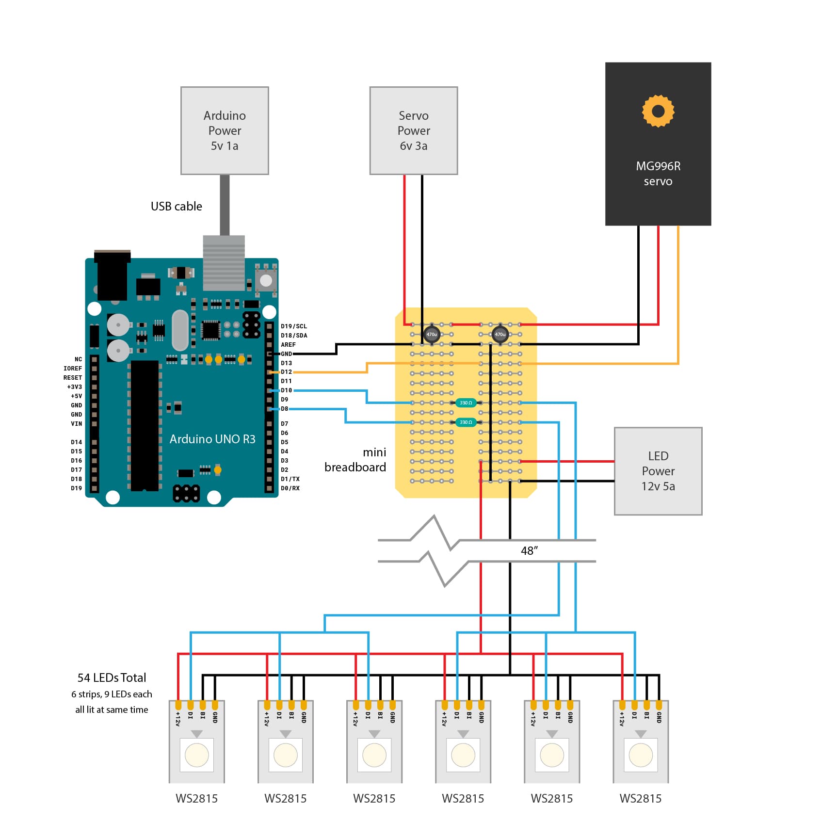
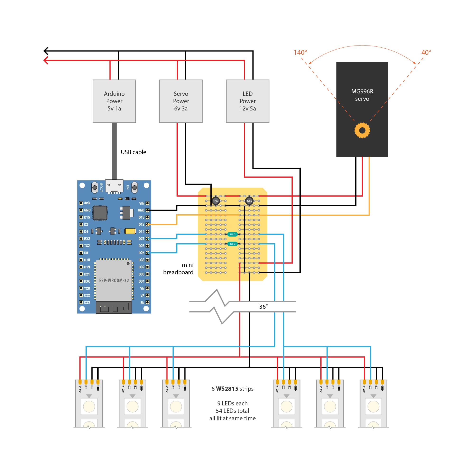
Hello! I'm trying to use a ESP-WROOM-32 to control a MG996R servo and two clusters of WS2815 strips, but I'm running into problems. The servo should sweep slowly from 40° to 140°, but it's very jerky and has large unexpected movements, and the LEDs aren't lighting up. The servo works relatively smoothly when I use the FastLED library, but goes bonkers when I use the NeoPixel library.
I've successfully made LED strip clusters like this before with an ESP32, but I was using WS2812s and not WS2815s, and used FastLED instead of NeoPixel too. I think I need to add a logic level shifter like a TXS0108E to bump the data signal from 3.3v to 5v, right? Or is there a simpler method that wouldn't invert the logic?
Here's my wiring diagram and all the code, which ChatGPT helped me with, which is likely part of the problem too. I'd love any feedback on how I can improve this!
#include <ESP32Servo.h>            // Use ESP32-specific Servo library
#include <Adafruit_NeoPixel.h>     // Include Adafruit NeoPixel library

#define LED_PIN_1 26               // First LED strip data pin
#define LED_PIN_2 33               // Second LED strip data pin
#define NUM_LEDS 9                 // Number of LEDs per strip
#define BRIGHTNESS_MIN 155         // Minimum brightness at 40 degrees
#define BRIGHTNESS_MAX 255         // Maximum brightness at 140 degrees
#define COLOR_CHANGE_INTERVAL 15000 // Color change interval in milliseconds

#define SERVO_PIN 12               // MG996R servo control pin
#define START_ANGLE 40             // Start angle
#define END_ANGLE 140              // End angle
#define UP_DURATION 4000           // Time to move from 40 to 140 degrees (in milliseconds)
#define DOWN_DURATION 6000         // Time to move from 140 to 40 degrees (in milliseconds)
#define SERVO_UPDATE_INTERVAL 20   // Servo update interval (in milliseconds)

Servo myServo;

Adafruit_NeoPixel strip1(NUM_LEDS, LED_PIN_1, NEO_GRB + NEO_KHZ800);
Adafruit_NeoPixel strip2(NUM_LEDS, LED_PIN_2, NEO_GRB + NEO_KHZ800);

uint32_t colors[] = {
  strip1.Color(255, 0, 255), // Magenta
  strip1.Color(0, 255, 255), // Teal
  strip1.Color(255, 165, 0), // Orange
  strip1.Color(0, 0, 255),   // Blue
  strip1.Color(255, 255, 0)  // Yellow
};

int colorIndex = 0;
unsigned long lastColorChangeTime = 0;
unsigned long servoStartTime = 0;
unsigned long lastServoUpdateTime = 0;
bool movingUp = true;
int currentAngle = START_ANGLE;
int lastAngle = START_ANGLE; // Track last servo angle

void setup() {
  Serial.begin(115200);

  // Initialize servo

  myServo.attach(SERVO_PIN, 500, 2500); // Set pulse range (500 to 2500 µs for MG996R)
  myServo.write(START_ANGLE); // Move servo to the initial start position - 40deg
  servoStartTime = millis();
  lastServoUpdateTime = millis();

  // Initialize LED strips
  strip1.begin();
  strip2.begin();
  strip1.setBrightness(BRIGHTNESS_MIN);
  strip2.setBrightness(BRIGHTNESS_MIN);
  strip1.show(); // Initialize to all LEDs off
  strip2.show();
  delay(10); // Give some time for LEDs to initialize

  // Set initial color
  setAllLEDs(colors[colorIndex]);
}

void loop() {
  // Update servo position
  updateServo();

  // Update LED colors and brightness
  updateLEDColor();
}

// Function to handle smooth servo movement
void updateServo() {
  unsigned long currentTime = millis();
  unsigned long duration = movingUp ? UP_DURATION : DOWN_DURATION;
  int startAngle = movingUp ? START_ANGLE : END_ANGLE;
  int endAngle = movingUp ? END_ANGLE : START_ANGLE;

  // Check if the servo needs to switch direction
  if (currentTime - servoStartTime >= duration) {
    servoStartTime = currentTime;
    movingUp = !movingUp;
  }

  // Update the servo position only if enough time has passed
  if (currentTime - lastServoUpdateTime >= SERVO_UPDATE_INTERVAL) {
    lastServoUpdateTime = currentTime;

    // Calculate smooth sine wave progress
    float progress = (float)(currentTime - servoStartTime) / duration;
    float sineProgress = (1 - cos(progress * PI)) / 2; // Smooth transition
    int targetAngle = startAngle + sineProgress * (endAngle - startAngle);

    // Update the servo only if the target angle has changed to avoid jitter
    if (abs(targetAngle - lastAngle) > 1) {
      myServo.write(targetAngle);
      lastAngle = targetAngle;

      // Adjust LED brightness based on servo position
      int brightness = map(targetAngle, START_ANGLE, END_ANGLE, BRIGHTNESS_MIN, BRIGHTNESS_MAX);
      strip1.setBrightness(brightness);
      strip2.setBrightness(brightness);
      strip1.show();
      strip2.show();
    }
  }
}

// Function to update the LED color fading effect
void updateLEDColor() {
  unsigned long currentTime = millis();

  // Change color every COLOR_CHANGE_INTERVAL milliseconds
  if (currentTime - lastColorChangeTime >= COLOR_CHANGE_INTERVAL) {
    lastColorChangeTime = currentTime;
    colorIndex = (colorIndex + 1) % (sizeof(colors) / sizeof(colors[0]));
  }

  // Smoothly transition between colors
  float progress = (float)(currentTime - lastColorChangeTime) / COLOR_CHANGE_INTERVAL;
  int nextColorIndex = (colorIndex + 1) % (sizeof(colors) / sizeof(colors[0]));
  uint32_t blendedColor = blendColor(colors[colorIndex], colors[nextColorIndex], progress * 255);

  // Update both LED strips with the new blended color
  setAllLEDs(blendedColor);
}

void setAllLEDs(uint32_t color) {
  for (int i = 0; i < NUM_LEDS; i++) {
    strip1.setPixelColor(i, color);
    strip2.setPixelColor(i, color);
  }
  strip1.show();
  strip2.show();
}

// Helper function to blend between two colors
uint32_t blendColor(uint32_t color1, uint32_t color2, uint8_t blendAmount) {
  uint8_t r1 = (color1 >> 16) & 0xFF;
  uint8_t g1 = (color1 >> 8) & 0xFF;
  uint8_t b1 = color1 & 0xFF;

  uint8_t r2 = (color2 >> 16) & 0xFF;
  uint8_t g2 = (color2 >> 8) & 0xFF;
  uint8_t b2 = color2 & 0xFF;

  uint8_t rBlend = r1 + ((r2 - r1) * blendAmount / 255);
  uint8_t gBlend = g1 + ((g2 - g1) * blendAmount / 255);
  uint8_t bBlend = b1 + ((b2 - b1) * blendAmount / 255);

  return strip1.Color(rBlend, gBlend, bBlend);
}