Hello guys I'm new to the community, and Arduino - electricity stuff too. I am learning ![]() I would like to create a led strip setup in my room, I've been searching the internet for a few days but locating everything and applying it to my vision is kinda hard. I tried to segment the post abit, all the questions/concerns would appear as 【?】 I will have 2 types of questions throughout this post, one is electronic wise, and the other will be Arduino code related ( but both actually the same topic )
I would like to create a led strip setup in my room, I've been searching the internet for a few days but locating everything and applying it to my vision is kinda hard. I tried to segment the post abit, all the questions/concerns would appear as 【?】 I will have 2 types of questions throughout this post, one is electronic wise, and the other will be Arduino code related ( but both actually the same topic )
━━━━━━━☆☆━━━━━━━
#1 Currently working setup
━━━━━━━☆☆━━━━━━━
■ General objective
【?】To find a way to replace the SP105E and Controll LED strips with Arduino ( via ESP8266 )

ᐛFull size view
━━━━━━━☆☆━━━━━━━
Questions block
━━━━━━━☆☆━━━━━━━
Lets start off with some "generic" questions I came across during the "figuring out" part
【1】a) Is it possible to run the Arduino board from the power supply,
b) if so, I would plug in via VIN + GND or 5V + GND,
c) do i need any resistor or other stuff - in front of the board.
d) Also as you can see from the pictures, the wifi module is "connected" to the Arduino board with the 5V ( and the board via VIN ) - does this connection need any resistor or other stuff - while I am chained from point a).
e) I've seen some pictures/posts that I couldn't use the USB connection ( to make changes on the Arduino board, I don't need a USB wifi connection / it has much less update cycles and can be done separately ) while the Arduino board would be powered by the PSU - is this true ? Is there any way around this - or would I need to disconnect the PSU power and connect PC USB.
【2】Data wire - 4 separate wires - to control the strips independently ? or use one and daisy chain it from say pin 5 of the Arduino - do I need resistors near the board or at the wire input near the leds ( in both variants 1 wire/4 ). General idea is to be able to program 4 of them independently - but also some common pattern e.g. 2+2, 4 is that FastLed library dependent or connection wise.
» Practical observation - I used a multimeter and plugged it directly into the FastLed connections I made on the PSU 5V out, when turing on it "gradually" fades towards 5V and stays there - so there is no burst above 5V and reduction.
» The purpose of the WiFi module is to send a signal to the Arduino board and control the strips via the digital outputs - with a simple website, you build in the WiFi module which sends a serial signal to turn certain things on/off. Scroll down to see the question related to this.
» The temperature is controlled via ds18b20 and the value is displayed on a website view ( runs via ESP - no data is transmitted to the Arduino ) . I don't plan on going more fancy, maybe a few more temp gages and other small modules to control humidity etc, no big installs or w/e. Will it be sufficient while connected to the power supply.
【3】When it comes to dimming, is that a FastLed implementation, or do I need an physical potentiometer or the data line?
I'd better ask all this before I experiment and ruin something.
Below you can see the exact details of everything I'm using.
◇───── Gear used ─────◇

● Arduino Uno Rev 3
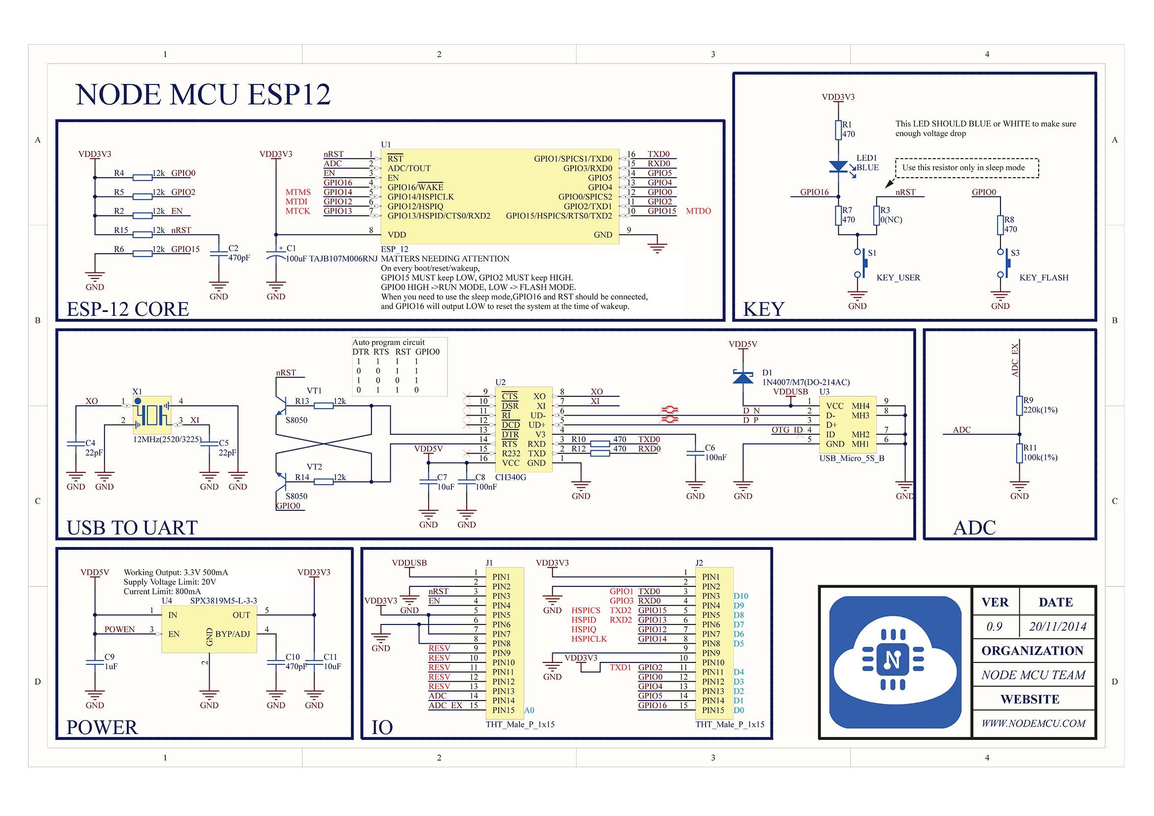
● ESP8266 Wemos NodeMCU V3 ( Wifi Module )
● Dallas ds18b20 ( Temperature meter )
◇─────────────────◇
◇───── Led Specification ─────◇
Each strip has 5 meters, I will be using 4. Below is a picture of the led connection cords which would be the strip number 2,3,4.
【4】The strip number 1 is a question how to connect - ? my idea would be just data of arduino and the start from PSU directly - similar as from*#1 Currently working setup -* the replacement part box

ᐛFull size - view link
WS2812B Strips
● DC 5V
● 30led / m
● 45w / 5 m = 9w/1m
● 5 meters
◇─────────────────◇
◇───── Power Supply ─────◇

ᐛFull size - side view link
ᐛFull size - back view link
● DC 5V impulse stabilized
● Max 70A/350W
◇─────────────────◇
【5】 Wifi - Arduino communication - taking a look at the gear used , first picture of the board. I got the pin RX of the ESP and routed over to TX on arduino. Everything is fine signal flows - but till arduino picks it up the delay is ~1-2 seconds. Thats why I have that single diode to represent the signal arrival.
Also my current board setup has an issue this has something to do with the Question Block question number 1 d), I assume it might have to do something with the 5V ? or some kind of misconfiguration that I am not aware of - since the serials are at the same value - perhaps I need a resistor there.
ESP8266 Board Code - Partial
#define WIFI_BOARD_LED 2 // wifi board led
void setup(){
  Serial.begin(115200);

  pinMode(WIFI_BOARD_LED, OUTPUT);
  digitalWrite(WIFI_BOARD_LED, HIGH);
}

// Based on what I click on the website, it sends B or C over the serial
String setDiodeState(String type){
 if(Led_Is_ON == 1){
    Led_Is_ON = 0;
    digitalWrite(WIFI_BOARD_LED, HIGH);
    Serial.print('B');
    return String("set off");
  }else{
     Led_Is_ON = 1;
     Serial.print('C');
     digitalWrite(WIFI_BOARD_LED, LOW);
     return String("set active");
  }
}
Arduino Board Code - Partial
#include <SoftwareSerial.h>
SoftwareSerial mySerial(0, 1); // RX, TX
void setup(void)
{
 mySerial.begin(115200);
}
void loop(void)
{
  testSerials();
}
// Specify what to do when arduino board recieves A,B or C from WIFI serial board ( Over RX-TX )
void testSerials(){
     while (mySerial.available() > 0){
      delay(2);
     data = mySerial.readString();
     Serial.println(data);
      if(data == 'A'){
        Serial.println("Recieved Startup");
      }

     else if(data[0] == 'B'){
        Serial.println("Off Led");
        digitalWrite(3, LOW);
      }

      else if(data[0] == 'C'){
         Serial.println("On Led");
         digitalWrite(3, HIGH);
        }
   }
}
I hope I was kinda clear - but if u do have any questions feel free to ask, If I come up with some questions ill post them aswell. Thank you for your time and have a nice day ![]()


