I'm still subject to the ridiculous 100 post limit (MHO), so I will respond to all of you in order in one post:
TomGeorge,
Yes, I have a DMM and I apologize for the "schematic." This is the kind of thing I do when I'm building, to give myself an idea of how to lay things out. I prefer not to make a true schematic until I'm nearly done, that way I kind of know how to make it less cluttered. There will probably be more features coming to this device.
CrossRoads,
Well done!
SteveMann,
Re: "Echo dot 5V device." Well I'm not sure why it says "input 12V DC and 1.25 A" on the bottom or why it came with a 12V power supply. This is an Echo Dot 3. Should I be contacting Amazon?
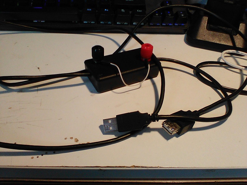
TomGeorge again,
Re: "Cutting power out of a USB cable." That is friggin' awesome. I totally could have come up with that if I weren't so stupid. I also like the added terminals. Nice touch. This is pretty much what I was looking for.
JCA34F and TomGeorge,
Re: "What PS am I using?" Originally I was planning to use the power supply that came with the Echo, but I added a servo motor as an indicator to which mode the device was set. When I did this, it exceeded the maximum current of that supply. I looked into servos that drew less current, but when I considered the maximum possible current draw with, lights, music, servo and whatever else Alexa needed (I measured MUCH less than 1.25A for the dot, even with the volume up so I don't know why it's spec'd so high), I decided to go with a different supply that was capable of something like 4A. Plenty of overhead. It had the additional feature of a plug on a wire that goes to the wall instead of a albeit small wall wart. This is intended as a gift to some friends that live in the UK. This would allow them to put a simple adapter on the plug and still use it, unlike the wall wart. In Germany the outlets are recessed so those wall warts don't work. I can't remember if they are in the UK or not, but either way this will work. That supply turned out to be problematic. After the servo moved to an indicated position, it kept moving around and I think the LEDs were flickering a little. When I looked at the serial monitor I saw that the value of the resistance from that resistor pack in the schematic was going out of range. I thought this was odd because I got that range by measureing it with my desktop power supply. So I switched back and it was solid. So I looked for another one online and found this one, which said "no noise." Gotta love that optimism. https://www.amazon.com/gp/product/B08C594VNP/ref=ppx_yo_dt_b_asin_title_o04_s00?ie=UTF8&psc=1
Well it did stabilize the values, in fact they were just as good as with my benchtop supply.
Re: "Not enough capacitance on regulator." The capacitance used is exactly what was called out in the data sheet. How much do you think I should use?
Paul__B,
Please tell me what is wrong with the 7805. It does get hot, but it puts out a steady 5.08V, can handle 1.5A if I remember correctly and I have a sizeable heat sink on it. I thought switchers induce more noise?
I haven't decided yet how many LEDs will be used. The original idea was one for each grill segment (bluetooth speaker very similar to this https://www.pinterest.com/pin/551972498063560143/). That would be 8 vertical segments, plus 16 horizontal segments plus 1 or 2 for the dial area. So total of 26 LEDs. However, I believe I have an idea which will shrink that number, but I haven't tested it yet. So I'm counting on 26.
I didn't understand the last half of your statement about 2/3 ". . . unless your main 5V supply is live." Maybe you could rephrase that sentence and use small words.
I like the idea of placing the switch on the ground side and pulling it up, but I don't understand why it is better.
- Actually the potentiometers ARE connected to ground. Not shown in drawing
- Smoke literally came out of the Nano. I meant the Nano board, not mine. When I removed it from my board and invsestigated the fried component was the zener diode connected to the USB port on the underside according to the internet, the source of ALL great things.
- It is a clone. I got this one probably a year ago so I don't have a reference. All I can tell you is I have to use the "old bootloader" to communicate.
- Well I agree, but I didn't know what. Since that was the only change I had made after plugging BOTH my 12V AND the USB in to monitor many times, I figured I must have shorted something with a solder blob. But nope! See my reply to ALL next.
ALL,
With the fried Nano off the board, I checked for a short. None. I checked resistance between the pin and ground with the switch disconnected and got 12K. I plugged in the power supply and saw 12.2VDC on the input to the regulator and 5.08V on the output. I first plugged the USB cable into a new Nano (clone), just freestanding, but with my finger on the diode. No problems. No heat. I then plugged the Nano into my board, no LED strip or switch. When I plugged in only the USB, no problem, no heat. I then plugged in the LED strip. No problem, no heat. Then the switch. Same thing. So I uploaded the software that checks the state of the switch and with the pull-down resistor in place I now read HIGH with the switch closed and LOW with the switch in the open configuration. . . as it should. I have NOT yet plugged in the 12V power supply (without the USB) to see if my last working sketch still functions without smoke. But this thread has not reached consensus. TomGeorge seems to think I should not plug them both in at the same time. Paul__B seems to think that is ok with a Nano. I'd like to get more feedback as I only have like one more Nano left and this is supposed to be a Christmas present. As I mentioned, I have plugged them both in many times, yet SOMETHING smoked the board and unless somehow I had a short, like maybe I wasn't careful and one of the potentiometers was touching the board (not likely), it kind of seems like having both supplies at one time was the most likely cause.
Sorry for the long post and thank you for the help.