Different gear motor speeds when connected to L293D driver

Ignore direction of the motors(for now).

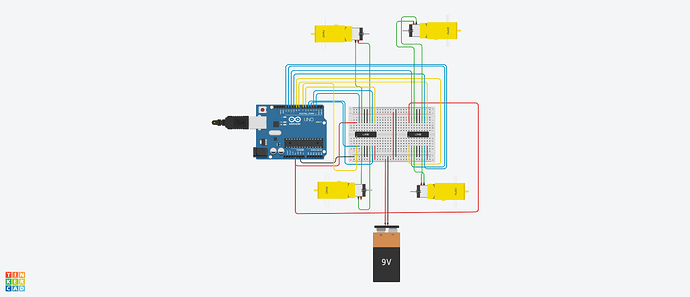
This is my connection diagram. Any and all improvements to the connections are welcome.
PS: I really cant change any of the components present here, due to material, financial and time constraints.

Bottom left motor seems to run at 210-224 rpm
Bottom right motor runs at 160-180 rpm
Top right motor runs at 210-224 rpm
Top left motor runs at 160-180 rpm


Code:

 
// Motor A connections

int enA = 7;

int in1 = 4;

int in2 = 5;

// Motor B connections

int enB = 6;

int in3 = 3;

int in4 = 2;

//Motor c

int enC = 9;

int in5 = 12;

int in6 = 13;

// Motor d connections

int enD = 8;

int in7 = 10;

int in8 = 11;

void setup() {

// Set all the motor control pins to outputs
pinMode(enA, OUTPUT);
pinMode(enB, OUTPUT);
pinMode(in1, OUTPUT);
pinMode(in2, OUTPUT);
pinMode(in3, OUTPUT);
pinMode(in4, OUTPUT);
pinMode(enC, OUTPUT);
pinMode(enD, OUTPUT);
pinMode(in5, OUTPUT);
pinMode(in6, OUTPUT);
pinMode(in7, OUTPUT);
pinMode(in8, OUTPUT);

  // Turn off motors - Initial state
digitalWrite(in1, LOW);
digitalWrite(in2, LOW);
digitalWrite(in3, LOW);
digitalWrite(in4, LOW);
digitalWrite(in5, LOW);
digitalWrite(in6, LOW);
digitalWrite(in7, LOW);
digitalWrite(in8, LOW);
}

void loop() {
  moveForward();
  delay(3000);
  motorOff();
  delay(1000);
}

void moveForward(){
  
  analogWrite(enA, 200);
  analogWrite(enB, 200);
  analogWrite(enC, 200);
  analogWrite(enD, 200);
  
  digitalWrite(in1, HIGH);
  digitalWrite(in2, LOW);
  digitalWrite(in3, HIGH);
  digitalWrite(in4, LOW);
  digitalWrite(in5, HIGH);
  digitalWrite(in6, LOW);
  digitalWrite(in7, HIGH);
  digitalWrite(in8, LOW);
}

void motorOff(){
  digitalWrite(in1, LOW);
  digitalWrite(in2, LOW);
  digitalWrite(in3, LOW);
  digitalWrite(in4, LOW);
  digitalWrite(in5, LOW);
  digitalWrite(in6, LOW);
  digitalWrite(in7, LOW);
  digitalWrite(in8, LOW);
}

Any changes to the code are also welcome
type or paste code here
EDIT: Tried this simulation in the real world, with a raspberry pi model 4B, and the corresponding python code, Worked almost successfully(3 motors worked, i suspect the 4th one didnt receive as much current to start), and in return fried my raspberry pi.
Hello vv123

Welcome to the worldbest Arduino forum ever.

You might design and code a function for motors.

e.g.

void motorControl (uint8_t motor,uint8_t direction, uint8_t speed)

So you can extremely simplify the use of the motors in the actual programme.

Have a nice day and enjoy coding in C++.

p.s. Generally speaking: Arrays and structs are your friends.

1 Like

A couple of warnings:

  1. It's not a good idea to have all this current going through a breadboard. Breadboards are designed for signals and small currents only. It's possible that the breadboard's connections are introducing some resistances which could explain part of the difference in speeds.

  2. 9V batteries are pretty useless for this type of project. They have a high internal resistance, so as soon as any serious current is drawn, the voltage will drop significantly. They also have very low capacity, so won't last long anyway.

  3. L293 (probably all motor drivers starting with "L") are old and inefficient designs with high voltage drops. There are much better drivers available these days.

  4. Motors are not guaranteed to run at the same speed even with exactly the same voltage. Robots need sensors to know if they are following the desired movements, even in a straight line, to give feedback so the MCU can continuously adjust the motor speeds.

With those warnings out of the way, have you tried swapping the motors around? What happens then?

EDIT: I just realised it's possible this is only a simulation and you don't have any real hardware connected. That would explain how you know the motor RPM: I guess Tinkercad shows the simulated RPM. in that case, I can't explain the differences is speeds. I doubt Tinkercad stimulates all those problems I described above, you would see those only in the real world. Maybe it would simulate the voltage drop off the L293, but that's probably it.

1 Like

9V batteries are pretty useless for this type of project. They have a high internal resistance, so as soon as any serious current is drawn, the voltage will drop significantly. They also have very low capacity, so won't last long anyway.

Any idea what other power source would be better or, if there is any requirement at all.

I doubt Tinkercad stimulates all those problems I described above, you would see those only in the real world. Maybe it would simulate the voltage drop off the L293, but that's probably it.

I Will be making this exact same setup in the real world, except with a pi instead of the arduino. Will update this post on this by EOD

I have seen this question come up before.
Two things to consider.

  1. pin 5 and 6 on and Uno have a different PWM frequency.
  2. motors with brushes have a preferred spin direction.

Leo..

With these old L293, I would suggest a holder for 6x AA or C cells. With more modern drivers, you might get away with 4xAA or C cells.

Or you could use an external 9V PSU with at least 2A output current. M

But I am guessing because you haven't given any specs for the motors or described what your project is about.

Yes, there is a requirement for power for the motors, they won't run without it. In other words, I'm not sure what you meant to ask there!

Don't forget that the PI's GPIO pins output only 3.3V compared to the Uno's 5V. Check what input voltage signal the L293 need as a minimum to recognise a HIGH level.

Any way to fix the different PWM frequency?
For your second point, considering that the bottom left and top left motor's orientation is same and direction of rotation is same, the speed still seems to be different.

Google "Arduino PWM frequency".
Different boards have different default PWM frequencies on different pins.
Pick four PWM pins that have the same default PWM frequency, or learn how to use timers.
Don't know which frequencies the Pi uses.

Or swap motors/drivers/pins around, and see which combination gives what speeds.
Leo..

Won't solve your "problem". To make brushed motors spin at a defined RPM you need to check the actual RPM and adjust your PWM accordingly - that's just as it is.

This topic was automatically closed 180 days after the last reply. New replies are no longer allowed.