Hello Everyone ![]()
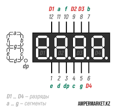
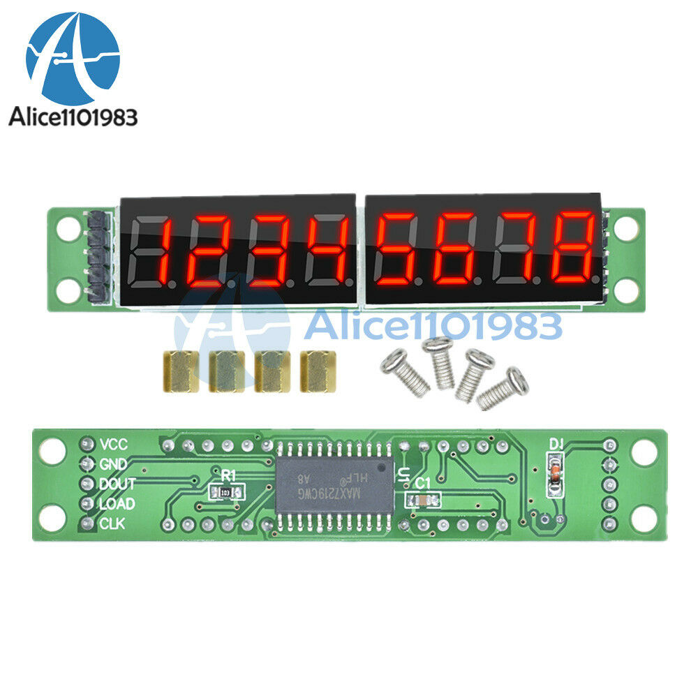
I've made a project using Arduino NANO, 7 segment 4 digit display Anode, 2 x 74HC959.
Here are the schematics:

I've got 2 identical displays, all connected to 1 Arduino NANO (in the code, you will see that its 3 display - that for the future, currently just the 2 displays are connected).
The resistor values are 470 [ohm].
Here is the code I'm using.
int clockPin[] = {7,10,13};
int latchPin[] = {6,9,12};
int dataPin[] = {5,8,11};

byte digits[] =   {B00001100, //0
                   B10111101, //1
                   B01101000, //2
                   B00111000, //3
                   B10011001, //4
                   B00011010, //5
                   B00001010, //6
                   B10111100, //7
                   B00001000, //8
                   B00011000  //9
                  };

int digit1, digit2, digit3, digit4;

void setup() {

  pinMode(clockPin[0], OUTPUT);
  pinMode(latchPin[0], OUTPUT);
  pinMode(dataPin[0], OUTPUT);

  pinMode(clockPin[1], OUTPUT);
  pinMode(latchPin[1], OUTPUT);
  pinMode(dataPin[1], OUTPUT);

  pinMode(clockPin[2], OUTPUT);
  pinMode(latchPin[2], OUTPUT);
  pinMode(dataPin[2], OUTPUT);

}

void loop() {

  showNumber(756,0);
  showNumber(74,1);

}


void showNumber (int num, int disp) {

  digit4 = num % 10;
  digit3 = (num / 10) % 10;
  digit2 = (num / 100) % 10;
  digit1 = (num / 1000) % 10;

  digitalWrite(latchPin[disp], LOW);
  shiftOut(dataPin[disp], clockPin[disp], MSBFIRST, B00001000); // X X X NUM
  shiftOut(dataPin[disp], clockPin[disp], MSBFIRST, digits[digit4]);
  digitalWrite(latchPin[disp], HIGH);
  delay(1);

  digitalWrite(latchPin[disp], LOW);
  shiftOut(dataPin[disp], clockPin[disp], MSBFIRST, B00000100); // X X NUM X
  shiftOut(dataPin[disp], clockPin[disp], MSBFIRST, digits[digit3]);
  digitalWrite(latchPin[disp], HIGH);
  delay(1);

  digitalWrite(latchPin[disp], LOW);
  shiftOut(dataPin[disp], clockPin[disp], MSBFIRST, B00000010); // X NUM X X
  shiftOut(dataPin[disp], clockPin[disp], MSBFIRST, digits[digit2]);
  digitalWrite(latchPin[disp], HIGH);
  delay(1);

  digitalWrite(latchPin[disp], LOW);
  shiftOut(dataPin[disp], clockPin[disp], MSBFIRST, B00000001); // NUM X X X
  shiftOut(dataPin[disp], clockPin[disp], MSBFIRST, digits[digit1]);
  digitalWrite(latchPin[disp], HIGH);
  delay(1);

}
As you can see from the code, I've created a function that receives 2 integers, and light up the corresponding LED display (int disp), with the number (int num).
The number that lights up are correct, and the digit is also correct.
The problem:
The first and last digits (left-to-right) lights up brighter than the rest digits, on display #1.
The first digit (left-to-right) lights up brighter than the rest digits, on display #2.

When connecting the output of the 74HC595 to oscilloscope (before resistors):
format: Display - Digit - active time - voltage
Display 1 - Digit 1 - 2.8 [sec] - 4.5 [V]
Display 1 - Digit 2 - 0.56 [sec] - 4.5 [V]
Display 1 - Digit 3 - 0.56 [sec] - 4.5 [V]
Display 1 - Digit 4 - 0.56 [sec] - 2.5 [V] - (no idea why there is a voltage drop here)
Cycle - 4.48 [sec]
Display 2 - Digit 1 - 2.8 [sec] - 4.5 [V]
Display 2 - Digit 2 - 0.56 [sec] - 4.5 [V]
Display 2 - Digit 3 - 0.56 [sec] - 4.5 [V]
Display 2 - Digit 4 - 0.56 [sec] - 4.5 [V]
Cycle - 4.48 [sec]

I'm guessing the problem is in my code, or the fact that maybe i don't quite understand the working of a shift register when implementing my code.
Any help would be greatly appreciated :))
Thanks in advance.
P.S.: it's my first schematics drawing, so please don't be hating if its a bit messy.
if any information is lacking for you to address the issue, please let me know ![]()