I have two boards connected, both with analog and digital parts, each part having a different ground plane.
My question: should I tie analog and digital grounds from one board before connecting it to the other board or should I have different GND and AGND connections between the boards ?
" tie analog and digital grounds from one board before connecting it to the other board"
Each board should have its own grounding resolved ultimately terminating at the power supply gnd.
Then it can connected to the other boards, which should connect back to the same power supply. If using a different power supply, then the one ground from each board should connect together. Otherwise you risk introducing ground loops and voltage potential differences and odd behavior and perhaps blown parts.
If you want to hook up to some device and share the same reference ground and even adjust the level - here is an intreserting design: Openenergymonitor - buffered voltage bias. Level is set using high ohm resistors and an op-amp keeps systems at the level set.
While into op-amps use another one to amplify/atenuate your signal.
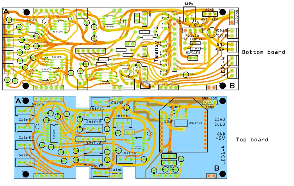
There are two boards interconnected on several places. The idea is to have two boards to reduce the footprint (major requirement). The top layer contains many trim pots, op-amps, an XBee board and LEDs. The bottom layer contains connections to analog sensors (left, top left, bottom left), instrumentation op-amps, the microcontroller (Teensy 3.1), as well as a connection to a LiPo cell (top right) and a +5V step-up voltage regulator. There are connections to a future secondary circuit (right) as well as a circuit to power and control a vibrating motor (bottom center). Bottom and top boards are interconnected at several places with pin headers. They connect top trim pots to adjust gain of the bottom instrumentation op-amps as well as the output of those op-amps to the top layer where additional analog treatment is done. Then the analog signals go back to the bottom layer and the microcontroller. The pin headers also carry serial signals to the XBee on the top board.
Brown zones in the top board are copper fill blockers from Fritzing, meant to separate analog and digital ground planes on the top board (to be added later). Similar work should be done on the lower board too.
The top right header connects both GND and AGND (as well as the +5V) from bottom board to top board.
Second picture displays where circuit's analog (blue) and digital (red) sections are (click on pictures to have them in higher resolution).
So, as the top board is more like an extension of the bottom one, should I really merge AGND and GND together on the top board?
Well, I think the fact that there is a question indicates that there is a flaw in the design. If instrumentation amplifiers need to be trimmed, then those signals should all be contained within one PCB. You shouldn't have the low-voltage external signals crossing boards.
Now if you had all the delicate inputs and trimpots on one board and then the amplified signals go off to another board for further volume/tone controls, then perhaps that's an acceptable solution. Then the noise from digital ground should be negligible compared to your analog signals.
Since it seems like this design is "close enough" then perhaps it's acceptable to have analog ground at one end of the two PCB's, like you're making a Faraday cage for your analog section. If that's the case, then you probably shouldn't have power and digital ground on the same header. Either way, I don't see your proposed solution as being wrong or naieve.
Do you have any similar equipment in your lab? Like maybe an oscilloscope? That has all of those issues, plus more. See if you can identify their grounding system. It may even be in the manual.
One way is to bring the ground planes together at a single point underneath the ADC or DAC
that converts the signals to from the analog domain. You have a star ground system then - see
the datasheets for various ADCs and DACs for this kind of layout advice too.
If you are not going to be converting analog signals to digital or vice versa, do not connect the
ground planes or supplies at all (except via resistors or RFC's) - injecting digital noise into
analog circuitry is best avoided where possible, although is does depend on how noisy the
digital components are and how sensitive the analog circuitry is at what frequencies.
For instance if you were amplifying audio from a quality condenser or moving coil mike, you
require the digital noise be down in the sub-microvolt range across the audio spectrum - not
achievable without good separation of ground and supply via RFC's and RC LPFs.
If however you are measuring a millivolt level temperature sensor reading with a bandwidth of
1Hz, you'd likely be OK as there is so little noise power in 1Hz of spectrum.