I am trying to troubleshoot with a student who is trying to learn how to use a 7 segment display. He has the display working (he can input a number into the code, and it will display on the screen fine), but things go haywire when he tried to introduce a button.
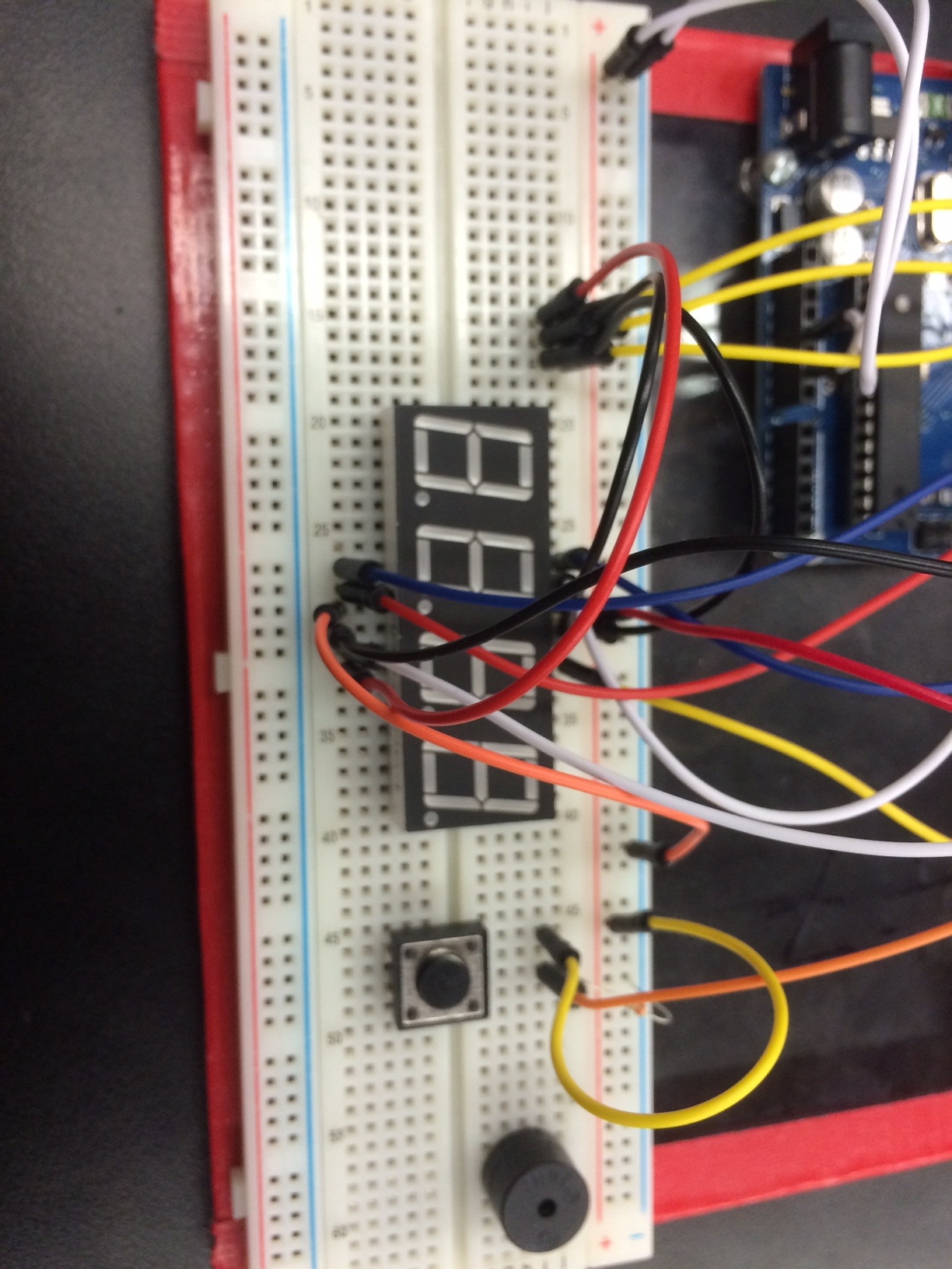
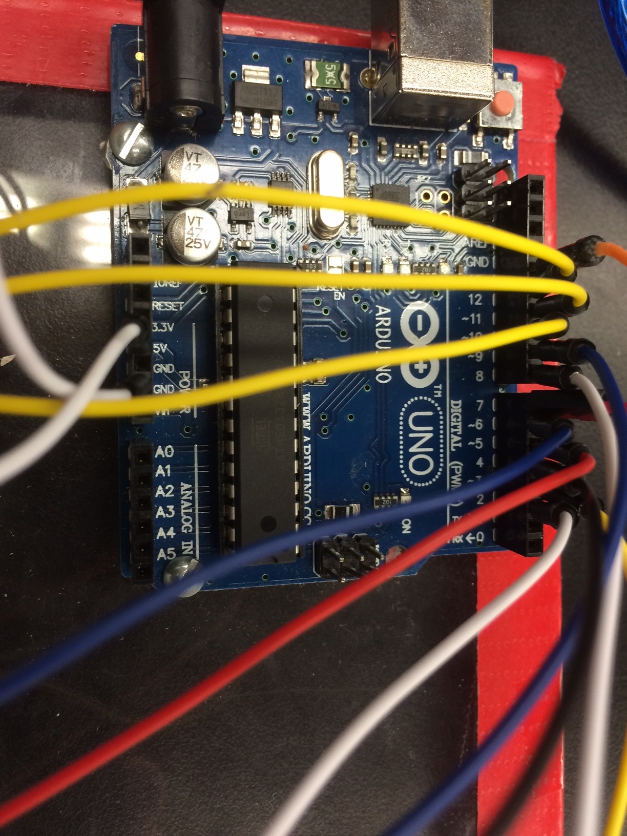
Just trying something simple, to make a "3" appear when a button is pushed, and a "2" when it isn't. However, when ever the button is pushed, the whole arduino and setup goes blank and loses power. It might be a wiring issue (I haven't taken a close look), but I wanted to run the code past to see if we are missing something. Below is the code for you to take a look at. I will also post a picture of the circuit, in case you are a wiring ninja and can spot an issue there.
int aPin = 2;  //            A
int bPin = 3;  //        ________
int cPin = 4;  //       |        |
int dPin = 5;  //     F |        | B
int ePin = 6;  //       |   G    |
int fPin = 7;  //       |________|
int gPin = 8;  //       |        |
int GND1 = 9;  //       |        |
int GND2 = 10; //     E |        | C
int GND3 = 11; //       |________|
int GND4 = 12; //
int num;       //           D
int dig1 = 0;
int dig2 = 0;
int dig3 = 0;
int dig4 = 0;
int DTime = 4;

int btn = 13;

void setup()
{
  pinMode(aPin, OUTPUT);
  pinMode(bPin, OUTPUT);
  pinMode(cPin, OUTPUT);
  pinMode(dPin, OUTPUT);
  pinMode(ePin, OUTPUT);
  pinMode(fPin, OUTPUT);
  pinMode(gPin, OUTPUT);
  pinMode(GND1, OUTPUT);
  pinMode(GND2, OUTPUT);
  pinMode(GND3, OUTPUT);
  pinMode(GND4, OUTPUT);
  Serial.begin(9600);
  pinMode(btn, INPUT_PULLUP);
}
void loop()
{
  digitalWrite( GND1, HIGH);
  digitalWrite( GND2, HIGH);
  digitalWrite( GND3, HIGH);
  digitalWrite( GND4, HIGH);

if(digitalRead(btn) == LOW)
{
  dig1 = 3;
  delay(5000);
}else{
  dig1 = 2;
}

 Serial.print(digitalRead(btn));


if (Serial.available() > 0)
{
  num = Serial.parseInt();
  Serial.println(num);
  dig1 = num / 1000;
  num = num - (dig1 * 1000);
  dig2 = num / 100;
  num = num - (dig2 * 100);
  dig3 = num / 10;
  dig4 = num - (dig3 *10);
}

  digitalWrite( GND4, LOW);   //digit 4
  pickNumber(dig4);
  delay(DTime);
  digitalWrite( GND4, HIGH);

  digitalWrite( GND3, LOW);   //digit 3
  pickNumber(dig3);
  delay(DTime);
  digitalWrite( GND3, HIGH);

  digitalWrite( GND2, LOW);   //digit 2
  pickNumber(dig2);
  delay(DTime);
  digitalWrite( GND2, HIGH);

  digitalWrite( GND1, LOW);   //digit 1
  pickNumber(dig1);
  delay(DTime);
  digitalWrite( GND1, HIGH);

}

void pickNumber(int x){
   switch(x){
     case 1:  one(); break;
     case 2:  two(); break;
     case 3:  three(); break;
     case 4:  four(); break;
     case 5:  five(); break;
     case 6:  six(); break;
     case 7:  seven(); break;
     case 8:  eight(); break;
     case 9:  nine(); break;
     case 10: down(); break;
     case 11: mid(); break;
     case 12: up(); break;
     case 13: downMid(); break;
     case 14: midUp(); break;
     case 15: downMidUp; break;
     default: zero(); break;
   }
}

void clearLEDs()
{
  digitalWrite(  2, LOW); // A
  digitalWrite(  3, LOW); // B
  digitalWrite(  4, LOW); // C
  digitalWrite(  5, LOW); // D
  digitalWrite(  6, LOW); // E
  digitalWrite(  7, LOW); // F
  digitalWrite(  8, LOW); // G
}

void one()
{
  digitalWrite( aPin, LOW);
  digitalWrite( bPin, HIGH);
  digitalWrite( cPin, HIGH);
  digitalWrite( dPin, LOW);
  digitalWrite( ePin, LOW);
  digitalWrite( fPin, LOW);
  digitalWrite( gPin, LOW);
}

void two()
{
  digitalWrite( aPin, HIGH);
  digitalWrite( bPin, HIGH);
  digitalWrite( cPin, LOW);
  digitalWrite( dPin, HIGH);
  digitalWrite( ePin, HIGH);
  digitalWrite( fPin, LOW);
  digitalWrite( gPin, HIGH);
}

void three()
{
  digitalWrite( aPin, HIGH);
  digitalWrite( bPin, HIGH);
  digitalWrite( cPin, HIGH);
  digitalWrite( dPin, HIGH);
  digitalWrite( ePin, LOW);
  digitalWrite( fPin, LOW);
  digitalWrite( gPin, HIGH);
}

void four()
{
  digitalWrite( aPin, LOW);
  digitalWrite( bPin, HIGH);
  digitalWrite( cPin, HIGH);
  digitalWrite( dPin, LOW);
  digitalWrite( ePin, LOW);
  digitalWrite( fPin, HIGH);
  digitalWrite( gPin, HIGH);
}

void five()
{
  digitalWrite( aPin, HIGH);
  digitalWrite( bPin, LOW);
  digitalWrite( cPin, HIGH);
  digitalWrite( dPin, HIGH);
  digitalWrite( ePin, LOW);
  digitalWrite( fPin, HIGH);
  digitalWrite( gPin, HIGH);
}

void six()
{
  digitalWrite( aPin, HIGH);
  digitalWrite( bPin, LOW);
  digitalWrite( cPin, HIGH);
  digitalWrite( dPin, HIGH);
  digitalWrite( ePin, HIGH);
  digitalWrite( fPin, HIGH);
  digitalWrite( gPin, HIGH);
}

void seven()
{
  digitalWrite( aPin, HIGH);
  digitalWrite( bPin, HIGH);
  digitalWrite( cPin, HIGH);
  digitalWrite( dPin, LOW);
  digitalWrite( ePin, LOW);
  digitalWrite( fPin, LOW);
  digitalWrite( gPin, LOW);
}

void eight()
{
  digitalWrite( aPin, HIGH);
  digitalWrite( bPin, HIGH);
  digitalWrite( cPin, HIGH);
  digitalWrite( dPin, HIGH);
  digitalWrite( ePin, HIGH);
  digitalWrite( fPin, HIGH);
  digitalWrite( gPin, HIGH);
}

void nine()
{
  digitalWrite( aPin, HIGH);
  digitalWrite( bPin, HIGH);
  digitalWrite( cPin, HIGH);
  digitalWrite( dPin, HIGH);
  digitalWrite( ePin, LOW);
  digitalWrite( fPin, HIGH);
  digitalWrite( gPin, HIGH);
}

void zero()
{
  digitalWrite( aPin, HIGH);
  digitalWrite( bPin, HIGH);
  digitalWrite( cPin, HIGH);
  digitalWrite( dPin, HIGH);
  digitalWrite( ePin, HIGH);
  digitalWrite( fPin, HIGH);
  digitalWrite( gPin, LOW);
}

void down()
{
  digitalWrite( aPin, LOW);
  digitalWrite( bPin, LOW);
  digitalWrite( cPin, LOW);
  digitalWrite( dPin, HIGH);
  digitalWrite( ePin, LOW);
  digitalWrite( fPin, LOW);
  digitalWrite( gPin, LOW);
}

void mid()
{
  digitalWrite( aPin, LOW);
  digitalWrite( bPin, LOW);
  digitalWrite( cPin, LOW);
  digitalWrite( dPin, LOW);
  digitalWrite( ePin, LOW);
  digitalWrite( fPin, LOW);
  digitalWrite( gPin, HIGH);
}

void up()
{
  digitalWrite( aPin, HIGH);
  digitalWrite( bPin, LOW);
  digitalWrite( cPin, LOW);
  digitalWrite( dPin, LOW);
  digitalWrite( ePin, LOW);
  digitalWrite( fPin, LOW);
  digitalWrite( gPin, LOW);
}

void downMid()
{
  digitalWrite( aPin, LOW);
  digitalWrite( bPin, LOW);
  digitalWrite( cPin, LOW);
  digitalWrite( dPin, HIGH);
  digitalWrite( ePin, LOW);
  digitalWrite( fPin, LOW);
  digitalWrite( gPin, HIGH);
}

void midUp()
{
  digitalWrite( aPin, HIGH);
  digitalWrite( bPin, LOW);
  digitalWrite( cPin, LOW);
  digitalWrite( dPin, LOW);
  digitalWrite( ePin, LOW);
  digitalWrite( fPin, LOW);
  digitalWrite( gPin, HIGH);
}

void downMidUp()
{
  digitalWrite( aPin, HIGH);
  digitalWrite( bPin, LOW);
  digitalWrite( cPin, LOW);
  digitalWrite( dPin, HIGH);
  digitalWrite( ePin, LOW);
  digitalWrite( fPin, LOW);
  digitalWrite( gPin, HIGH);
}