I am using a 4-digit,7 segment display for a project.Initially, it worked perfectly, butAfter some time, the display suddenly started malfunctioning and I faced many problems. Therefore, I decided to test it. I am using an arduino uno and COMMON_ANODE has worked for me.
The problems I face are:
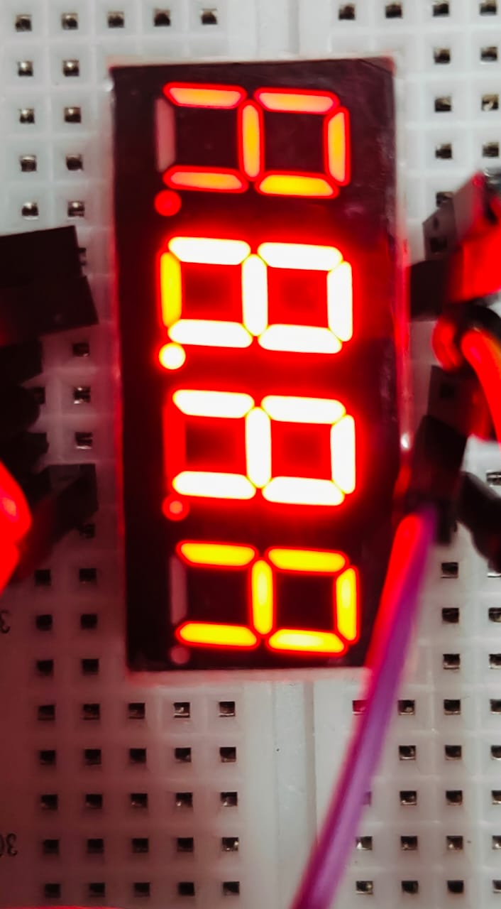
2 dim digits and one segment being dim/off in all 4 digits.
The code:
#include <SevSeg.h>
SevSeg sevseg;
void setup() {
  // put your setup code here, to run once:
  Serial.begin(9600);  // start communication
  byte numDigits = 4;
  byte digitPins[] = { 10, 11, 12, 13 };
  byte segmentPins[] = { 6, 7, 8, 9, 2, 3, 4, 5 };
  bool resistorsOnSegments = false;      // 'false' means resistors are on digit pins
  byte hardwareConfig = COMMON_CATHODE;  // See README.md for options
  bool updateWithDelays = false;         // Default 'false' is Recommended
  bool leadingZeros = false;             // Use 'true' if you'd like to keep the leading zeros
  bool disableDecPoint = false;          // Use 'true' if your decimal point doesn't exist or isn't connected. Then, you only need to specify 7 segmentPins[]

  sevseg.setBrightness(100);
  sevseg.begin(hardwareConfig, numDigits, digitPins, segmentPins, resistorsOnSegments,
               updateWithDelays, leadingZeros, disableDecPoint);
}

void loop() {
  // put your main code here, to run repeatedly:
  sevseg.setNumber(8888, 0);
  sevseg.refreshDisplay();
}
P.S : I am a first time poster and a beginner so I have probably made a silly mistake.I hope I have provided all the required info and if any info is required, please tell me.I hope you can view my circuit digram.
I did fix some issues by tinkering with the circuit but this problem is not getting solved, please do help me.
The wiring diagram is uninterpretable, because we don't know how the display is wired. But I suspect that you are burning out port pins.
A port pin can support only about 20 mA, either "going in", or "going out". The pins that select the segment anodes or cathodes are probably expected to conduct many times that.
You need transistors to drive the anodes or cathodes.
Thanks for the suggestion could you suggest a way to cross verify if it is Common cathode or common anode
Btw I have a 4 digit display labelled : 3461BS-1 348
Make sure the display pins are inserted correctly in the breadboard, and not shifted over one slot.
What value resistors are you using? I think you can use it without transistors if you use higher value resistors (at least 1K, but 2.2K would be better) on each of the eight segment lines, with no resistors on the common anode pins. 1K resistors would have the anode pins sourcing 25mA for an "8.", which is really pushing it. 2.2K, or even 1.5K, should work ok, but might not be very bright.
Edit: No, I'm wrong. Your wiring should work. See below.
That means the library will use multiplexing by segment instead of multiplexing by digit. And that means that only one segment line is turned on at a time, but all the common anodes (digits) that use that segment are turned on at the same time. So the maximum load on a segment line is four segments if that segment is lit up on all four digits, which an Arduino should be able to do without resorting to transistors at, say, 5mA per segment or so. And the maximum load on an anode line is one segment.
So your original drawing should work if you have the display and the Arduino inserted in the right places in the breadboard, and if the anode resistors are reasonable. But you do need to change code to reflect that you're using a common anode display.
You can confirm that it's common anode by removing all the jumpers to the display, then connecting the 5V pin of your Arduino to pin 12 of the display through a resistor, and pin 1 of the display to an Arduino GND pin. That should light up a segment.
The 10K resistors are way too high. I am surprised you can see the display lighting at all, except in a very dark room.
I think @ShermanP is correct in post #13 (not post #11), resistorsOnSegments = false will cause the library to multiplex by segment, rather than by digit, so only 1 resistor per digit is required, and each pin is only handling current for a single segment at any instant in time, so no transistor is needed, although this will limit the brightness of the display.
In your case, the average current flowing through each segment would be around (5-1.8)/10000/8 = 26uA which is so small that it could barely be seen. For this reason I think your circuit isn't as you have shown. Please post some bright, clear photos of the whole circuit from above.