Hi,
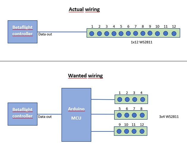
my quadrocopter (betaflight firmware) has only one digital RGB LED output. I want to divide one RGB strip into several separate lights. Due to the elimination of the length of data PIN used between the lights, I want to use some small Arduino MCU to split LED lights to several groups see. picture. Arduino MCU should listen to input and divide into groups to output. Betaflight uses some own library to use digital LEDs. Is this possible? In Arduino I'm a newbie. Thanks.
Is it possible to alter the LED section of the Betaflight code to fit Your needs? Adding an Mcu looks like overkill.
That's relatively hard. The data stream is high frequency, so capturing it and reproduce it will be a challenge, more so if you are creating multiple smart LED data streams.
But Betaflight only has one LED output. Why not just wire the segments in a daisy chain, dOut to the next dIn like they are meant to be, and use Betaflight's configurator to make each part do what you want?
Explain why you need multiple streams. Smart LEDs are smart, exploit that using code, not more complicate hardware.
You could also fork Betaflight and add more LED channels to it. Sounds like about as much fun, and almost as pointless.
a7
I thought that if some MCU creates data stream in high frequency, then my new similar MCU could capture this stream and remodel according to some algorithm.
I'm starting to understand. My idea was LED lights will be wired to the star connection to eliminate the length of data pin cable between lights, this is important because of the weight of the drone, the less copper cables the lighter construction. Each light out of four is placed on the far side of the drone. The new MCU could only weigh a few grams.
A similar controller already exists, however, is controlled by PWM signal and works differently than I need. RGB LEDs are not controlled separately.
Wouldn't simple extension wires weigh less than an entire MCU board? Even if it's a small one?
Please show a dimensional diagram of how the strips are physically positioned.
Because, your request as stated is far too difficult to implement on most Arduino.
Are the separate strips getting the same data? Just wire their dIn lines together and feed them all the FC output signal.
If not, say more about what the different strips will do and where exactly they are on the quadcopter, and an idea of how big it is, that is to say how far apart are they and how close to sources of power and ground each strip may find itself.
And for weight… there's no way, even if you could do what you want, that some stranded #28 wire is going to weigh more than another processor board.
How many pixels on a strip? You don't need 14 AWG wire for power and ground, either. Look at the size of the wires on typical quadcopter LED boards.
a7
Here is the position of the LED strips on the drone, I will use this strip - 5pcs LEDs per light. You may be right to put the wires will be much easier, I just wanted to know that good idea is construct this project. You're right, I rejecting my idea and I will connect wires with digital LEDs strips like usual.
There I only see 10/ and 20/. And they've underestimated the current substantially.
On the other hand, planning for all LEDs on full bright all the time can be silly.
But if you have 5 LEDs at 60 mA maximum brightness, that's still only 300 mA, and those tiny wires the strips come with will be entirely adequate.
I use #24 or #28 stranded wire for exactly this purpose, always works out fine.
I do have to say, however, that I don't usually trick out my FPV aircraft in this way. The LOS stuff gets LEDs, but more functional like head and tail lights and markers on the bottom to assist in maintaining my sense of orientation.
You'll save time ditching the impossible task, more time to fly.
a7
This topic was automatically closed 180 days after the last reply. New replies are no longer allowed.

