DigitalWrite in loop without repeat

hi all,

i have these code for a small project, i am trying to make it works once but still unable, any suggestions?

tried a lot of search but didn't found what i need.

what i am trying or want is

IF D10 is HIGH
D11 become HIGH then delay 5 secs and then become LOW

then it shouldn't repeat till D10 change state or repeat

and when D10 is LOW should follow ELSE in same pattern and follow again for once if D10 is HIGH

my code:


Thanks
void setup() {
 pinMode(11, OUTPUT);
 pinMode(10, INPUT); 
 
}
  
void loop() {
   if (digitalRead(10) == HIGH)
  {
    digitalWrite(11, HIGH);
    
    delay(5000);
    
    digitalWrite(11, LOW);


  }
else
{
  digitalWrite(11, LOW);
  
  delay(5000);
  
  
  digitalWrite(11, HIGH);
  
}
}


There’s your secret…
Currently you’re testing if D10 is high, but never confirm whether it has gone low between cycles.

Maybe the state change detection is what you need? This is not just for buttons, but for any digital signal where you need to detect a certain transition or edge (high to low or low to high).

Hello
Your sektch needs some basic functions:

  • Timer - based on the mother of all Arduino timers - BLINKWITHOUTDELAY example of the IDE
  • Button handler - as already mentioned by groundFungus

Have a nice day and enjoy coding in C++.

I don't understand your description of the functionality

if input D10 becomes HIGH switch D11 HIGH
keep D11 switched HIGH for 5 seconds
after 5 seconds switch D11 low

As long as input D10 stays HIGH do nothing
If input D10 has becomes low start checking again for input D10 becoming HIGH again?

You should post a description that names all details just in normal words.
mixing code and writing about "this" or "again" or "it" leads to a lot of misunderstandings.

In this description you should avoid all programming-terms as you might have mis-conceptions about the programming terms.

Another way of showing your wanted program-behaviour is to draw a freehand timing diagram. One diagram for each case that can occur.

best regards Stefan

i try to make it simple,

whenever D10 is high it should on the led (D11) for 5 secs and then stop.
whenever D10 is LOW led should again on for 5 secs and then stop.

with this codes (blinkwithoutdelay included) led keep on blinking (repeating code) after every 5 secs even if 12 is high constantly,

what i need is it should do only once.

hope i explained my issue well this time.

Hello greatpam
If you are familar with coding in C++ it will be simple.
Make a structure containing all pin and timing information, a method will take care about these information will process it to get the desired project goal.

Have a nice day and enjoy coding in C++.

NO.

draw a timing diagram that shows all the different cases that can occur

Do you mean:
whenever D10 becomes high it should on the led (D11) for 5 secs and then stop.
whenever D10 becomes LOW led should again on for 5 secs and then stop.

This would make much more sense.
You need a change state detection to accomplish this as @groundFungus already mentioned.

but state change detections has to wait D10 to get low

i only want that led remain on just for 5 secs,

what i can add after:

to stop repeating from here or jobdone type so it doens't repeat the same steps even if there is no change in D10 status

I have no idea what you mean by to stop repeating from here or jobdone type

post a handrawn timing diagram that shows how D10 and D11 should be switched low high

without seeing a timing diagram the only thing I can suggest is

your code has to detect any kind of state-change
to distinguish between now it is time to repeat the one-time-action of 5 seconds LED on then LED off from

it is not yet time to repeat the one-time-action of 5 seconds LED on then LED off

tips how to improve your posting style

best regards Stefan

this example will switch ON a LED by button press and
switch off after a specific time

/*
  by noiasca 
  http://werner.rothschopf.net/202003_arduino_retriggerbares_nachlaufrelais.htm
*/

const byte buttonPin = A0;     
const byte outputPin = 2;      

void tickButtonLed()
{
  static uint32_t previousMillis = 0;  
  if (digitalRead(buttonPin) == LOW) {
    digitalWrite(outputPin, HIGH);
    previousMillis = millis();         
  }
  if (millis() - previousMillis > 3 * 1000UL && digitalRead(outputPin) == HIGH)  
  {
    digitalWrite(outputPin, LOW);
  }
}

void setup() {
  pinMode(buttonPin, INPUT_PULLUP);
  pinMode(outputPin, OUTPUT);
}

void loop() {
  tickButtonLed();
}

its a retriggerable monoflop.
retriggerable, because during on time you could extend the time with an additional button press.

be careful, I'm using a button with INPUT_PULLUP and check the button against LOW. You might want to change this.

just for explaining my point again, please refer screenshot attached

whenever i switch the button to right side the led should on for just 5 secs and after 5 sec it should turn off until i switch the button again

it can be possible?

is it a momentary button which connects only as long as you press it or is it a
switch which keeps the connection after a you moved it to right?

it keeps the connection till i manually switch to off

You do mean until you have

  • moved the switch to the left (nothing more happens)

  • and moved it to the right again (LED goes on)

don't you? Can you see why your prose is continuously ambiguous, and frustrates attempts to write your code for you?

a7

first: yes
second: LED goes on for 5 secs only

i am unable to understand where i am expressing wrong..

You still do not get the point that your description needs more precision

In your picture the switch is shown with level on the right
grafik

What is still unclear is
if the switch has been turned to the left
grafik

if just this has happened. switched to the left without having switched it back again to the right.

Is this the situation where the LED should be switched on again for 5 seconds

or

different thing

switch is on the right side
grafik

switch is pulled to the left
grafik

then again the switch is pulled to the right
grafik

This means you have pulled the switch left-right which is different than just switch pulled left.

So shall the LED be switched on for 5 seconds after pulling left-right?

in both cases you have a state

change

state-change

and you should finally finally finally read

how state-change-detection is programmed

I recommend to all users here to

not

post any code until greatpam has schown some "greatness" by posting an attempt how a state-change can be programmed.

Hello greatpam
Stay tuned, I´ve to collect some objects for a sketch proposal.
Have a nice day and enjoy coding in C++.

@greatpam

first I would like that you check a basic example how to read a switch


https://www.arduino.cc/en/Tutorial/BuiltInExamples/DigitalReadSerial

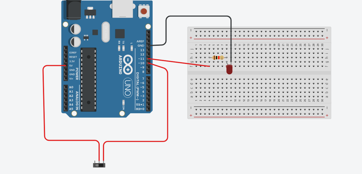
you see, Arduino is using an external pull down resistor to be able to read a button/switch which connects the pin to VCC.
Please read the description.

Do you understand that you need an external pulldown to be able to read the HIGH?

If yes, I ask you to either correct your wiring (with an external pulldown) or use the internal pullup and rewire your switch to close it to GND.

Let us know the outcome and post an udpated schematic of your wiring.