Hello,
I have bought current hall sensor for 3 phase. Obviously from Aliexpress :-(. And the wiring description on label and on website is confused as I'm not sure which one is currect.
If anyone already might using this sensor, I would appreciate if anyone can provide a real picture and experience which port are correct for power up device and which port for connecting on arduino.
Thanks in advance...
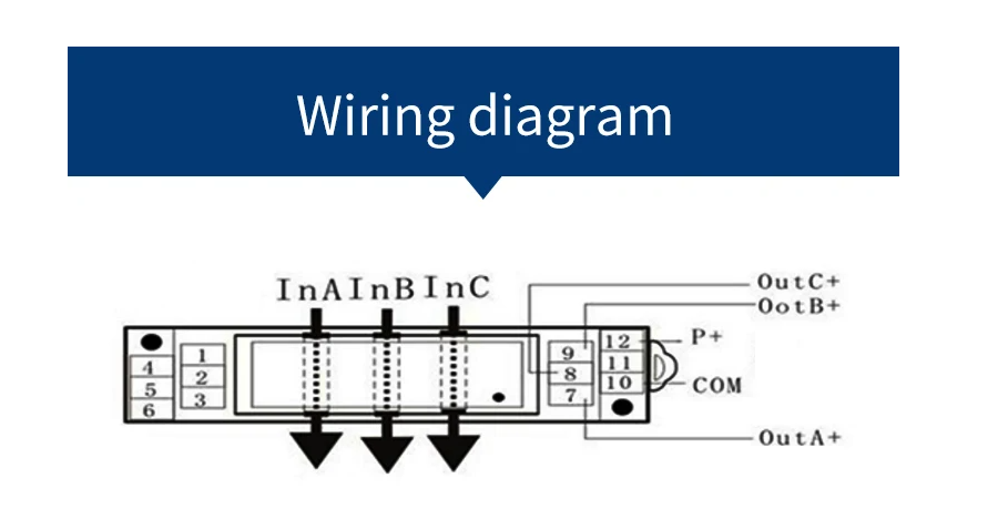
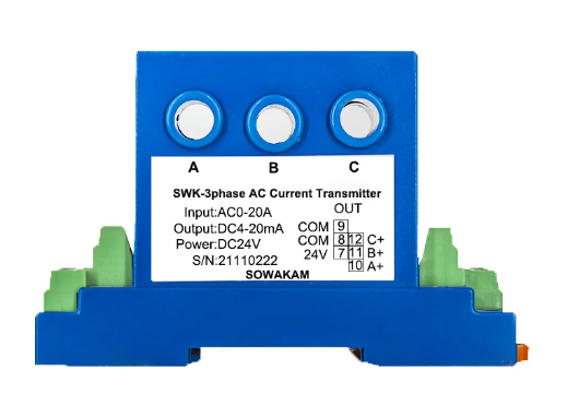
Thanks for you comments, but if you compare pictures the OutPin and power supply ports are opposite. Like Wiring Diagram is having on 7 = OutA+, and label on product have on 7 = 24V. This what concerns me, which one is correct?
I would rely on the label on the device. It requires 24vdc for power and outputs a 4-20 mADC signal proportional to 0-20 amps A/C on each phase. You will need to use a resistor in each current loop to convert the signals to a voltage that your Arduino can measure. The resistor value will depend on what reference voltage you use.
You will need to connect the Arduino ground to the common pin of the transmitter. Each resistor will also connect between its signal positive and common.
This is how I would look at it.
Using for example an Arduino Uno Rev 3 I would make sure my ADC reference was 5.0 volts. I would place a 250 ohm precision 1% resistor from each current out to ground so the 4 ~ 20 mA which is proportional to current becomes 1.0 to 5.0 volts.
I would use A0, A1 and A2 on your Arduino board and in your code map the analog values to get your current for each phase.
Calculate power in your code. The formula for power of a 3-phase circuit is Power = Voltage (V) x Current (I) x Power Factor (PF) x square root of three . If we assume the load on the circuit is resistive only, power factor is unity (or one) which reduces the formula to P = V x I x square root of three.