i have project (vu meter) that pulls ~7.5 Amps for total design.
is there a way to use multiple smaller 5400 diode to protect at higher currents?
i know paralleling works with high risks so i guess series would be about the same for risks.
i already have a regulator booster that works awesome to supply the design, however, i had a BY550-400 that i salvaged from a board that crapped out. i know it wasn't rated but i was expecting the worse. besides, the vu meter does not run 100% draw constantly. it lasted several months longer than i thought.
i have several 5400 diodes and would like to see if there IS an ideal way to use them without spending money for part and shipping cost.
although i am using 12vdc, would a full rectifier be of use somehow? i know it would have a bigger vd but if i can get amperage rating high enough and it would work. i have several of them also.
please help with suggestions on readings somewhere or design tips.
Where and how are you using these diodes? What are you using them to protect against?
You know, if you're in the US, you could get some appropriately beefy diodes for around $5 shipped from digikey, or $10 shipped with plenty of spares (USPS cheapest domestic shipping is like $3.50), and have them in 3 business days.
I expect an answer to what are you trying to protect?
You must see some threat from somewhere, where do you see it?
It is not normal to protect power lines with clamping diodes.
i basically just want to protect system from any type of issues that may arise.
Sorry not possible even if you are flying this to the moon.
The standard way is to assume that any one component can fail in any mode. Therefore your scenario of:-
protect system in case the supply goes wacky and sends over voltage
Is not going to happen because this relies more than one faulty component within the power supply. In all my many years I have never known a power supply to put out higher than the rated voltage due to a fault.
protect power supply from any issues that may happen
The power supply has it's own protection circuits built in.
I think that you are worrying too much about a possible failure. There is no single magic bullet, in fact multiple magic bullets are in short supply.
I have worked professionally on getting a system to be as reliable as possible, it is not something you can bolt on afterwards you need to consider every aspect of the design and make an assessment of every component and consequences if it fails short or open.
You must try and ensure that there is no SPF ( Single Point of Failure ) in the system as a whole. It is not an easy task and requires a lot of work.
Not sure where this diode is in the circuit.
It could for reverse polarity protection if it is at the start of the power inlet. Is there any chance of the power supply being disconnected and reconnected the wrong way round?
Everyone (and their search engine) knows what a '4148 is, its the architypal small signal
diode in every circuit out there practically! Its there with the '555 and 7805
Grumpy_Mike:
Is not going to happen because this relies more than one faulty component within the power supply. In all my many years I have never known a power supply to put out higher than the rated voltage due to a fault.
Lucky you!
While linear regulators are fairly unlikely to fail "high", switchmode supplies most certainly can and do. It only takes a (single component) failure in the regulator feedback.
I had - back before ADSL - a nice net interface box - used with a dial-up modem - to keep me on the Internet until one day all the indicator lights were on but clearly no-one was home.
The 5V regulated switchmode supply (in a rather large "plug pack" form with a British plug) was merrily supplying some nine or ten volts, which rose to 15 when it was disconnected from the newly-minted dummy load.
Now a possible reason why you might not have seen such failures, or in general fewer switchmode failures than we do here with "universal" supplies, is that you have only half the mains supply voltage.
Grumpy_Mike:
The power supply has it's own protection circuits built in.
Maybe. All switchmode supplies clearly should have a "crowbar" protection on the output rail, very few actually do (and need I make comment about Chinese origin and design?).
again, thanks for replies. i feel every little thing helps me learn something. i hope the following info helps clarify.
Did you mean 1N4148 when you said "4148"? Please use complete part numbers, it reduces the chance of misunderstandings.
it is a 1n4148 switching diode on each audio input into the led board(s)
Not sure where this diode is in the circuit.
It could for reverse polarity protection if it is at the start of the power inlet. Is there any chance of the power supply being disconnected and reconnected the wrong way round?
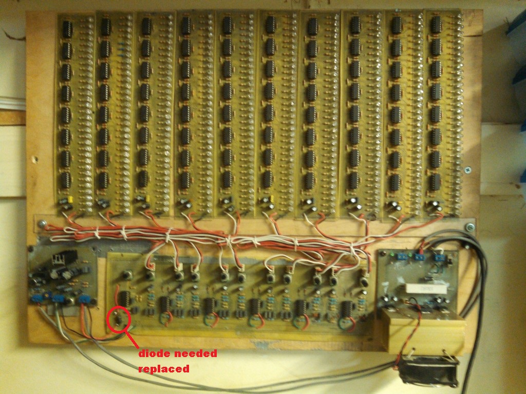
the larger diode i question is on power supply into system, on crossover.
since i am the only one that will connect leads, no chance of reversal since board is marked with polarity, unless i am having a very bad day. the board is hanging on my wall and i do not plan on rewiring anything unless i need to.
i have a 7812 with 2955 boosted circuit supplying 2 voltage leads (far right with fan)
1st lead to a lm386 mic amp and single tda2050 amp (far left)
2nd lead into crossover board which also feeds all ten led boards.
the crossover has 6-lm324's
each vu board has 32 leds (each with 390R limiter for 20mA each led) and 8-lm324's
this is a design i got from another person from the web. i tweaked the limiting resistors to my leds and changed layout of board design but it is still original design i received.