Thanks. It is same.
As I can see, you set if time = 0, but I think there is a time, which exist (as single digit), only not converted in number.
Also, sometimes when digit blank in serial, thinks that there is some hidden digit under it, which can't see.
That interference, whatever its cause, result, usually with two digit flickering (random of 6) one by another.
Well done! Thanks!
I tried very hard to see with naked eye, even with camera, is there flickering, but I can't see any of them. I think this problem are solved.
How you do that?
Is that mean if no clear numbers, then show number from before, like freeze it (only in 1/8 of second) ?
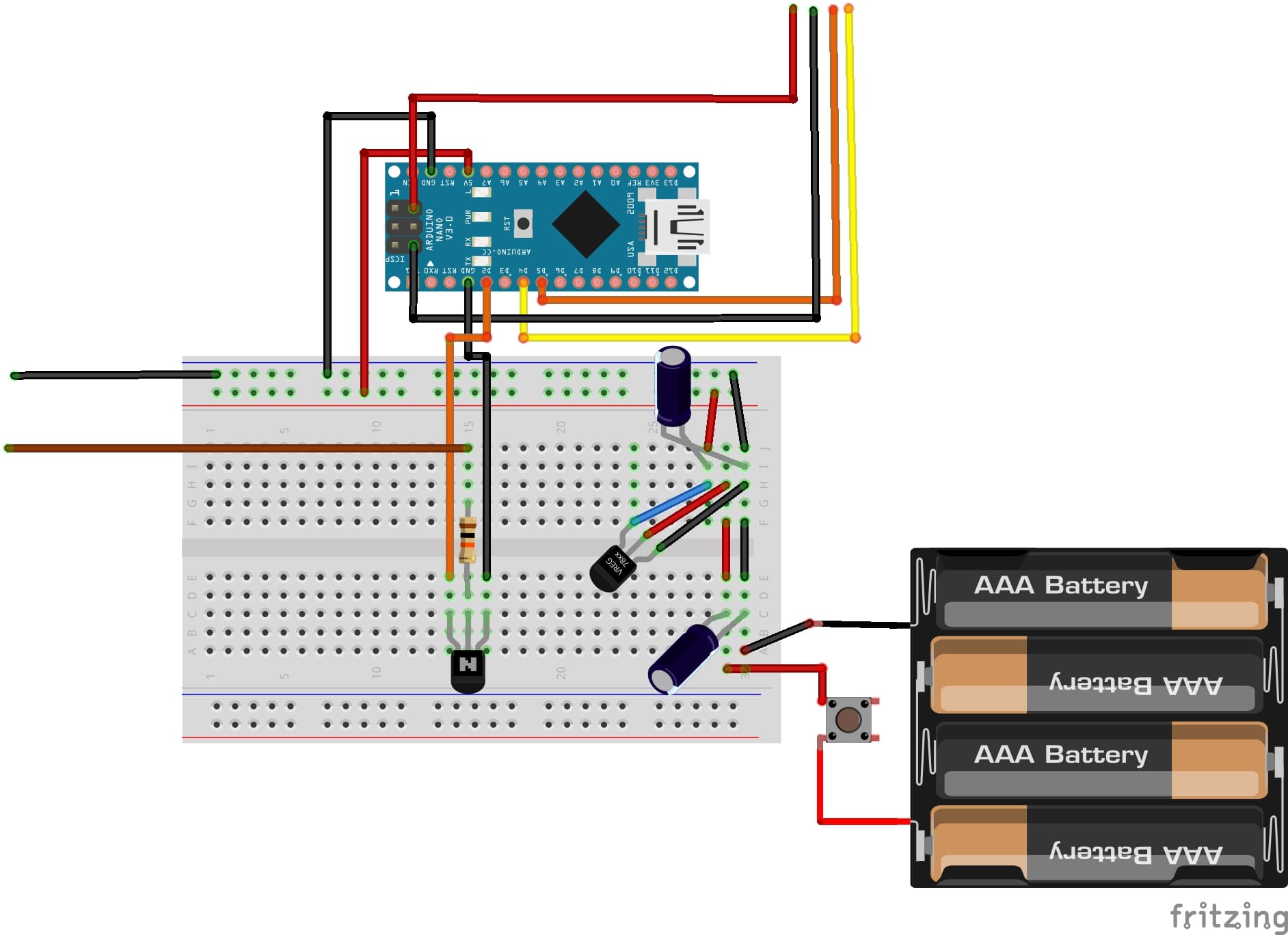
Now, if you don't mind, please allow me to remove last placed resistor, so that will be only one resistor (like scheme #55), can I do that?
No, there are 2. They are both on the output side of the regulator. One is 100nF and the other is 1000uF. I don't think you need anything as big as 1000uF for your circuit, so try the 1uF as the data sheet suggests, plus the 1uF on the input of the regulator also. If you have problems, increase the cap on the output side to 10uF. The voltage of the caps does not matter as long as they are above the maximum battery voltage.
For the same value of capacitance, a lower voltage cap will probably be physically smaller, and may be cheaper. Those are the only advantages. If the size and price is ok for your project, a higher voltage cap will be fine.
I am looking how much exactly volts have 4xAAA, non-rechargeable. Only video I found is here.
From that I see that all have 6.0 to 6.1v.
So, now the biggest question, stay on 1700 or use 1702. Can be 1700 burned when exceed this 0.1v? I think not.
The second question is minimum input of this two. Is that mean if regulator have higher minimum voltage input, it will shut down earlier (when device use power) than regulator with the lowest minimum input voltage? And after that battery can be used and working in other devices which have no such big limited minimum input?
Linear regulators like these do not cut out when they can no longer output 5V. They just output less than 5V.
The mcp2702 has a drop-out of 625mV. The mcp1700 has a drop-out voltage of only 178mV.
That means that as the battery voltage falls, the 1702 output will drop below 5V when the input voltage reaches about 5.6V. After that, the output voltage will remain about 0.6V below the input, so when the input voltage falls to 5.0V, the output will be about 4.4V.
With the 1700, the output will drop below 5V when the input voltage falls to about 5.2V. When the input voltage has fallen to 5.0V, the output will be 4.8V.
What we don't know is what minimum voltage the Nano and the display need to continue to operate. The Nano should be ok down to around 3.8V, and maybe lower, but it is not guaranteed. I don't know about the display.
So the 1700 might give a longer battery life. But it has the disadvantage that it could be damaged by input voltage over 6V.
I see now that I make mistake in post, where we both not noticed it. It is not 6.1 for all batteries, must be 1.6 per battery!! LOL
Anyway, I bought 4xAAA Duracell, which are accessible to everyone, and they have 6.39v! Don't know how long need to voltage drop and how much will drop, but for sure, the 1702 is necessary there.
Don't worry, I will be using rechargeable all time while timer is with me and save planet
I got rest of parts.
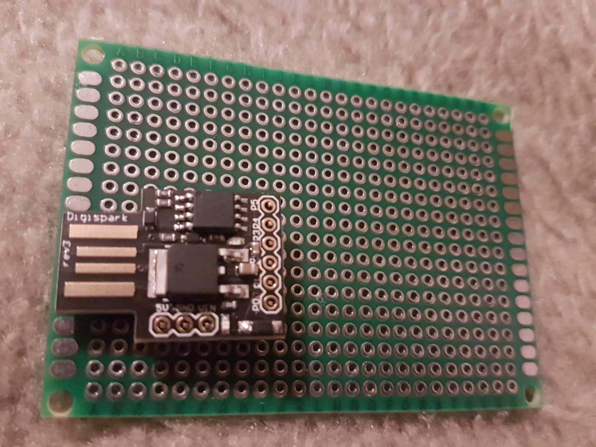
For Digispark my position will be good like bottom left (or right). Later, idea is cut upper board to half.
Can you tell me is that good way to soldering Digispark, like on picture? (I mean, the 'tip' must be inside board?).
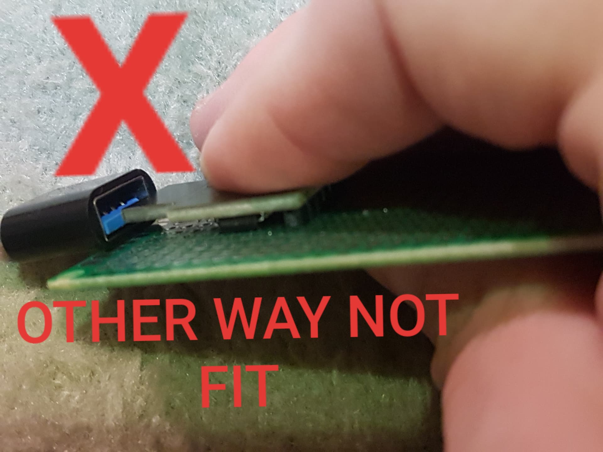
And I found that this way, where are chips on the top, is the best way when you want to connect USB, because if you rotate Digi top/bottom 180°, the blue part in USB (picture) won't come smoothly, that means you must pull Digispark for 1mm UP to insert USB, which will be impossible when will be soldered.
The way like on picture, this type of USB go smoothly.
I assume that Digispark 'USB' must stay open and be accessible for project if someone in future want to do upgrade? Otherwise, I can close it up in enclosure, and problem done.