Hello, I recently bought a display:
https://pl.aliexpress.com/item/1005003943508410.html?spm=a2g0o.order_list.order_list_main.11.26ae1c24AU2sa6&gatewayAdapt=glo2pol
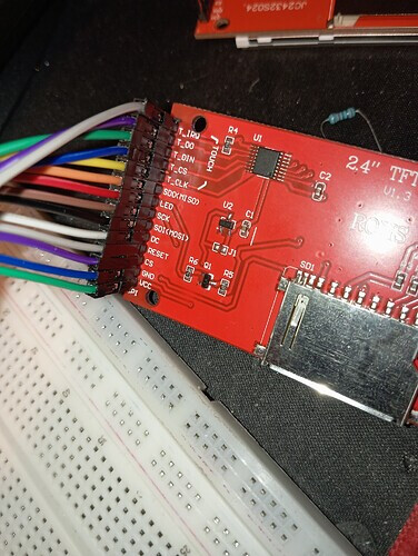
touchscreen and connected it to Arduino Uno as shown in the official instructions:


and I recorded their code:
// IMPORTANT: LCDWIKI_SPI LIBRARY MUST BE SPECIFICALLY
// CONFIGURED FOR EITHER THE TFT SHIELD OR THE BREAKOUT BOARD.

//This program is a demo of displaying string

//when using the BREAKOUT BOARD only and using these hardware spi lines to the LCD,
//the SDA pin and SCK pin is defined by the system and can't be modified.
//if you don't need to control the LED pin,you can set it to 3.3V and set the pin definition to -1.
//other pins can be defined by youself,for example
//pin usage as follow:
//             CS  DC/RS  RESET  SDI/MOSI  SDO/MISO  SCK  LED    VCC     GND
//Arduino Uno  A5   A3     A4      11        12      13   A0   5V/3.3V   GND

//Remember to set the pins to suit your display module!

/***********************************************************************************
* @attention
*
* THE PRESENT FIRMWARE WHICH IS FOR GUIDANCE ONLY AIMS AT PROVIDING CUSTOMERS
* WITH CODING INFORMATION REGARDING THEIR PRODUCTS IN ORDER FOR THEM TO SAVE
* TIME. AS A RESULT, QD electronic SHALL NOT BE HELD LIABLE FOR ANYA
* DIRECT, INDIRECT OR CONSEQUENTIAL DAMAGES WITH RESPECT TO ANY CLAIMS ARISING
* FROM THE CONTENT OF SUCH FIRMWARE AND/OR THE USE MADE BY CUSTOMERS OF THE
* CODING INFORMATION CONTAINED HEREIN IN CONNECTION WITH THEIR PRODUCTS.
**********************************************************************************/
#include <LCDWIKI_GUI.h> //Core graphics library
#include <LCDWIKI_SPI.h> //Hardware-specific library

//paramters define
#define MODEL ILI9341
#define CS    A5
#define CD    A3
#define RST   A4
#define MOSI  11
#define MISO  12
#define SCK   13
#define LED   A0   //if you don't need to control the LED pin,you should set it to -1 and set it to 3.3V

//the definiens of software spi mode as follow:
//if the IC model is known or the modules is unreadable,you can use this constructed function
LCDWIKI_SPI mylcd(MODEL,CS,CD,MISO,MOSI,RST,SCK,LED); //model,cs,dc,miso,mosi,reset,sck,led
//if the IC model is not known and the modules is readable,you can use this constructed function
//LCDWIKI_SPI mylcd(240,320,CS,CD,MISO,MOSI,RST,SCK,LED); //width,height,cs,dc,miso,mosi,reset,sck,led

//define some colour values
#define BLACK   0x0000
#define BLUE    0x001F
#define RED     0xF800
#define GREEN   0x07E0
#define CYAN    0x07FF
#define MAGENTA 0xF81F
#define YELLOW  0xFFE0
#define WHITE   0xFFFF

void setup()
{
  mylcd.Init_LCD();
  mylcd.Fill_Screen(BLACK);
}

void loop()
{
  mylcd.Set_Text_Mode(0);
  //display 1 times string
  mylcd.Fill_Screen(0x0000);
  mylcd.Set_Text_colour(RED);
  mylcd.Set_Text_Back_colour(BLACK);
  mylcd.Set_Text_Size(1);
  mylcd.Print_String("Hello World!", 0, 0);
  mylcd.Print_Number_Float(01234.56789, 2, 0, 8, '.', 0, ' ');
  mylcd.Print_Number_Int(0xDEADBEF, 0, 16, 0, ' ',16);
  //mylcd.Print_String("DEADBEF", 0, 16);

  //display 2 times string
  mylcd.Set_Text_colour(GREEN);
  mylcd.Set_Text_Size(2);
  mylcd.Print_String("Hello World!", 0, 40);
  mylcd.Print_Number_Float(01234.56789, 2, 0, 56, '.', 0, ' ');
  mylcd.Print_Number_Int(0xDEADBEF, 0, 72, 0, ' ',16);
  //mylcd.Print_String("DEADBEEF", 0, 72);

  //display 3 times string
  mylcd.Set_Text_colour(BLUE);
  mylcd.Set_Text_Size(3);
  mylcd.Print_String("Hello World!", 0, 104);
  mylcd.Print_Number_Float(01234.56789, 2, 0, 128, '.', 0, ' ');
  mylcd.Print_Number_Int(0xDEADBEF, 0, 152, 0, ' ',16);
 // mylcd.Print_String("DEADBEEF", 0, 152);

  //display 4 times string
  mylcd.Set_Text_colour(WHITE);
  mylcd.Set_Text_Size(4);
  mylcd.Print_String("Hello!", 0, 192);

  //display 5 times string
  mylcd.Set_Text_colour(YELLOW);
  mylcd.Set_Text_Size(5);
  mylcd.Print_String("Hello!", 0, 224);

  //display 6 times string
  mylcd.Set_Text_colour(RED);
  mylcd.Set_Text_Size(6);
  mylcd.Print_String("Hello!", 0, 266);

  delay(3000);
}
but it keeps showing me white and nothing happens
do you know what the problem might be?