Hi
I am having a problem getting a DisplayTech 162F to work with an Arduino MEGA. the first problem I perceived to be lack of voltage I could only get just over 4 volts from the Arduino board so I put in the extra power supply which feeds the Arduino MEGA board with power as well as the Breadboard. I now have 5 volts on both boards.
I ought to at this stage say that the code and circuit have been validated in as much as the code and circuit work with another LCD display but will not with the 162F. See pictures.
Anyone else suffered this problem ??
any help gratefully received
"Does not work" conveys no useful information. Are there any blocks displayed? Does the backlight come on? Does the contrast adjustment have any effect?
Hi, sorry for my lack of description, the back light works fine, however I cannot see any text regardless of how the pot is set.
Occasionally I see what i can only describe as random noise it shows parts of a block but nothing resembling text. I cannot see the grids constantly, nothing except a blue screen.
LCD displays that have their row of pins above and to the left of the display all seem to have the same pinout, with pin 1 near the edge of the board and pin 16 closer to the center.
On the other hand LCD displays that have their row of pins below and to the left of the display (as I believe yours does) tend to use a different pinout, and there are several variations.
You will have to look at a datasheet to determine your pinout and connect the wires appropriately. It took me less than a minute to search for and find the datasheet for your device.
Don
Hi, I have checked the pin out from the data sheet many times already, and will do it again, I like you thought this was the most likely source of the problem given that the code works and the circuit works with a different type display.
I am seriously wondering if i have a bad batch.
Why don't you post a photo and let us double check your wiring.
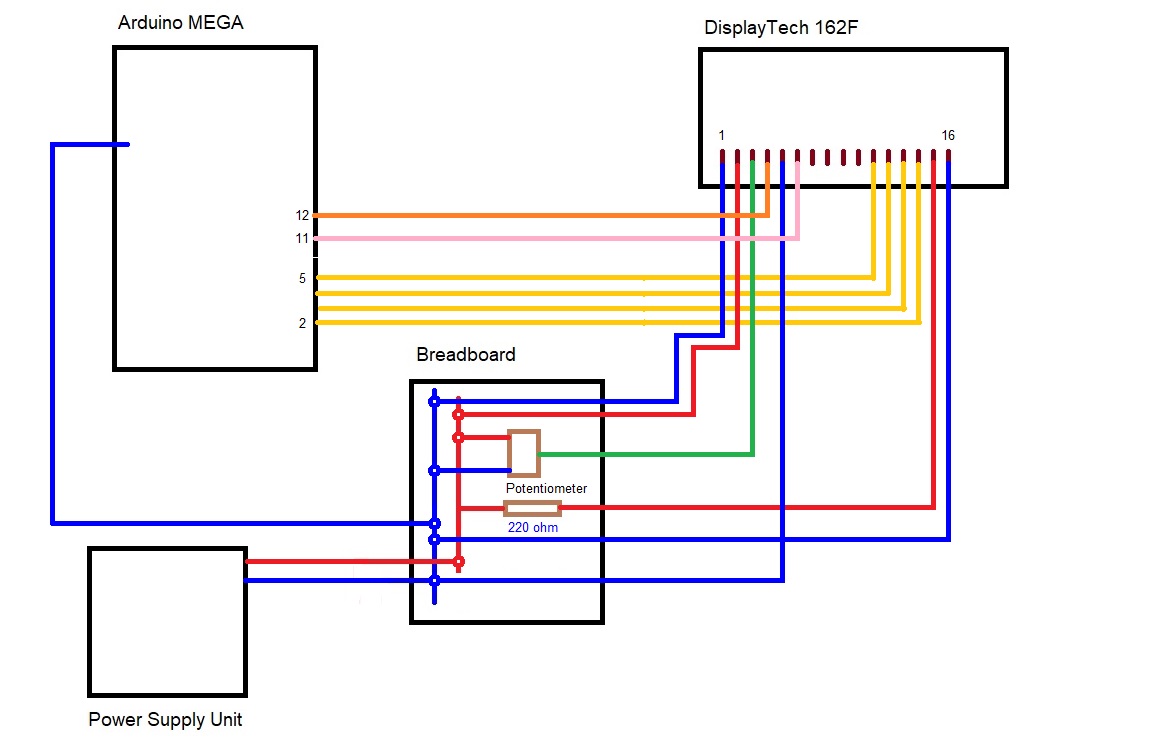
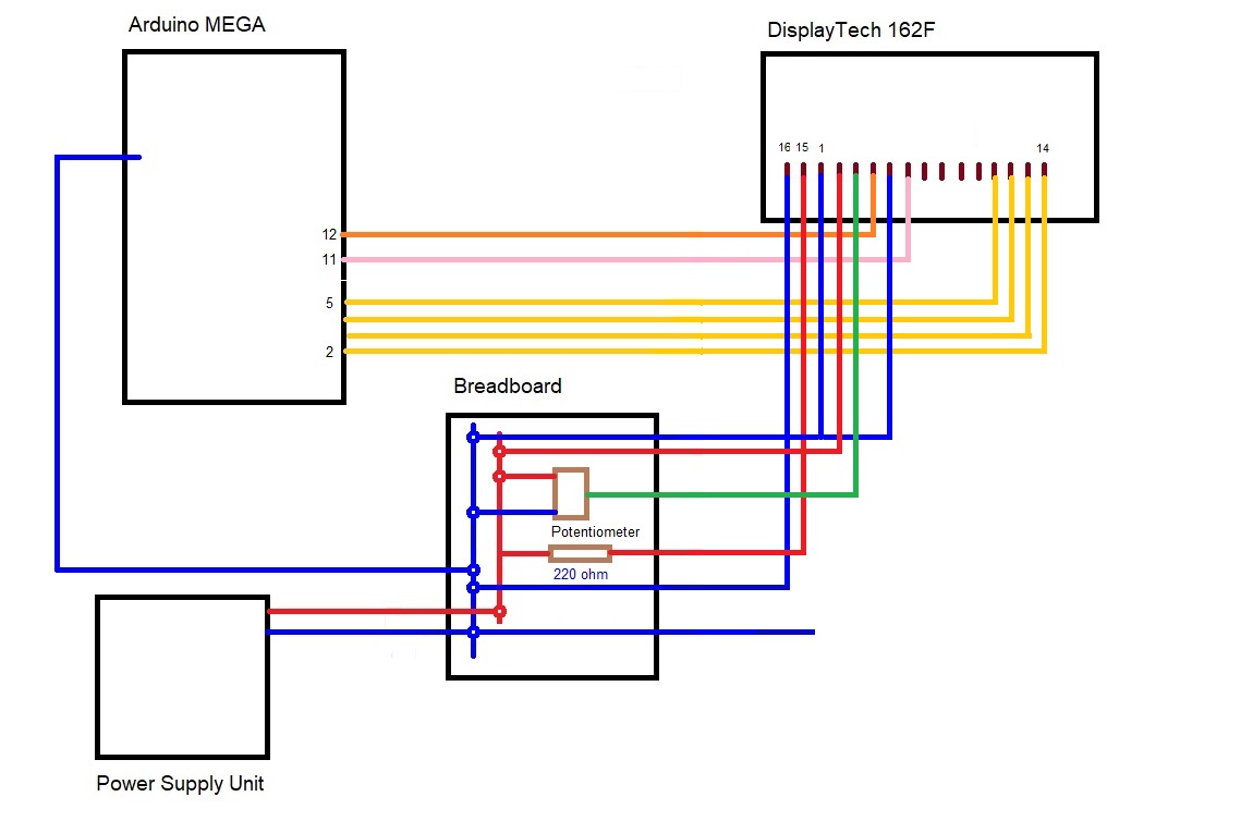
A 'wiring' diagram such as the one you provided in your original post is supposed to depict the actual physical location of the connections on the devices. Yours shows pin 1 near the left edge of the board and pin 16 closer to the center.
The 'mechanical drawing' on page 7 of the datasheet that I downloaded shows pin 14 near the left edge of the board and pins 1, 15, and 16 closer to the center.
I suspect that the majority of your wiring (all except the backlight) is exactly backwards.
Don
Hi, unfortunately I am away from my workbench for the next few weeks, when I get back I will take a video of the circuit.
So hopefully I can eradicate any wiring error
Merry Xmas
LesC
Hi Everyone, I am back from my travels but still have the same problem my display won't work.
I have attached the code and the wiring diagram ( file called header) I have successfully run a 'standard' LCD using this circuit and program file IMG_0357.jpg .
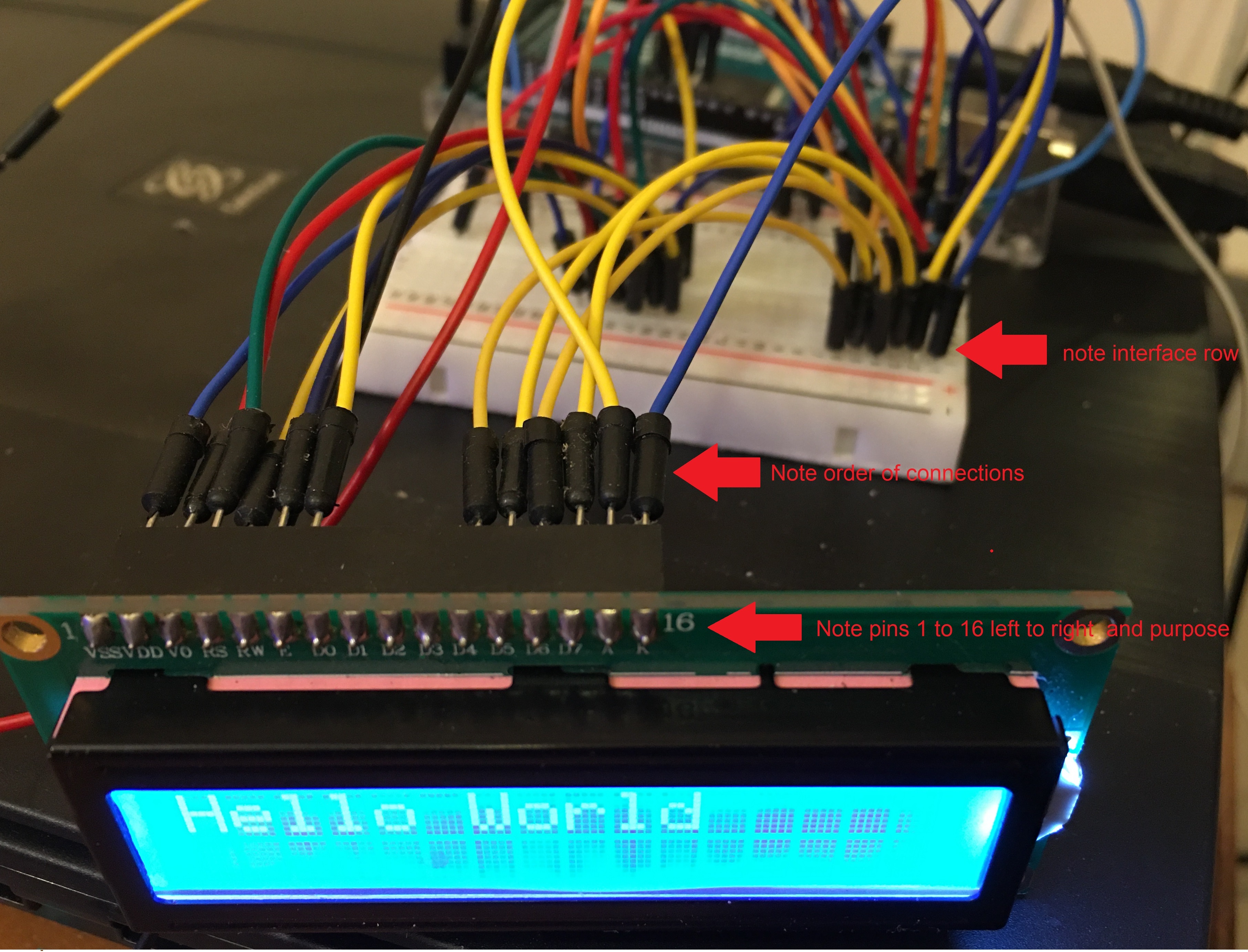
The order of the connections on the interface row on the pin out board follows the order of the connections on the Display from left to right pins 1 to 16.
I then have substituted the Displaytech display leaving everything else untouched. IMG_0354.jpg shows the interface row with both displays detached.
Image file IMG_0370.jpg shows the Displaytech display in place. As far as I can ascertain the wiring is correct and the program is correct. To me that suggests in initialisation problem ( library problem ) or a hardware problem with the display .
I cannot attach all files as the Forum limit is rather low, drop me an email address to see photographs
any help gratefully received
regards
Les Collier
Hello_World_LCD_Display_Standard.ino (515 Bytes)
Once again....
floresta:
Why don't you post a photo and let us double check your wiring.
. . .
I suspect that the majority of your wiring (all except the backlight) is exactly backwards.
Until we see a photograph of your connections I don't think we can be of much help.
Don
I'll try one file at a time
hi I am having trouble making the graphics files small eneough to fit on here can I suggest you mail me and i will mail the files back to you via E-mail
My e-mail address is lescolliershustoke@virginmedia.com
Go on. The photo in #11 shows that you know how to wire a regular 16x2 i.e. pins #1 .. #16
If your other LCD has #15,#16 then #1..#14, you connect the pins accordingly.
I would expect both LCDs to work fine.
I have never seen an LCD with female header strip.
Male header strip can plug into your breadboard. You can use trimmed connecting wire for 1-14.
And change the backlight wires (15, 16) for the appropriate LCD.
David.
Hi I think I finally managed to get a photo of the wiring
Only you can make any sense out the rats nest.
The LCD is upside down. Not easy to read.
I can't see any external electronics. When you consider that the LCD has 6 signals + 5V + GND, it does not need that many wires.
David.
Les_Collier:
Hi I think I finally managed to get a photo of the wiring
I think the yellow wire is connected to the wrong pin.
Unless the photograph of your connections allows us to unambiguously follow each wire from one end to the other it really doesn't help us determine if the connections are correct.
Don
Hi
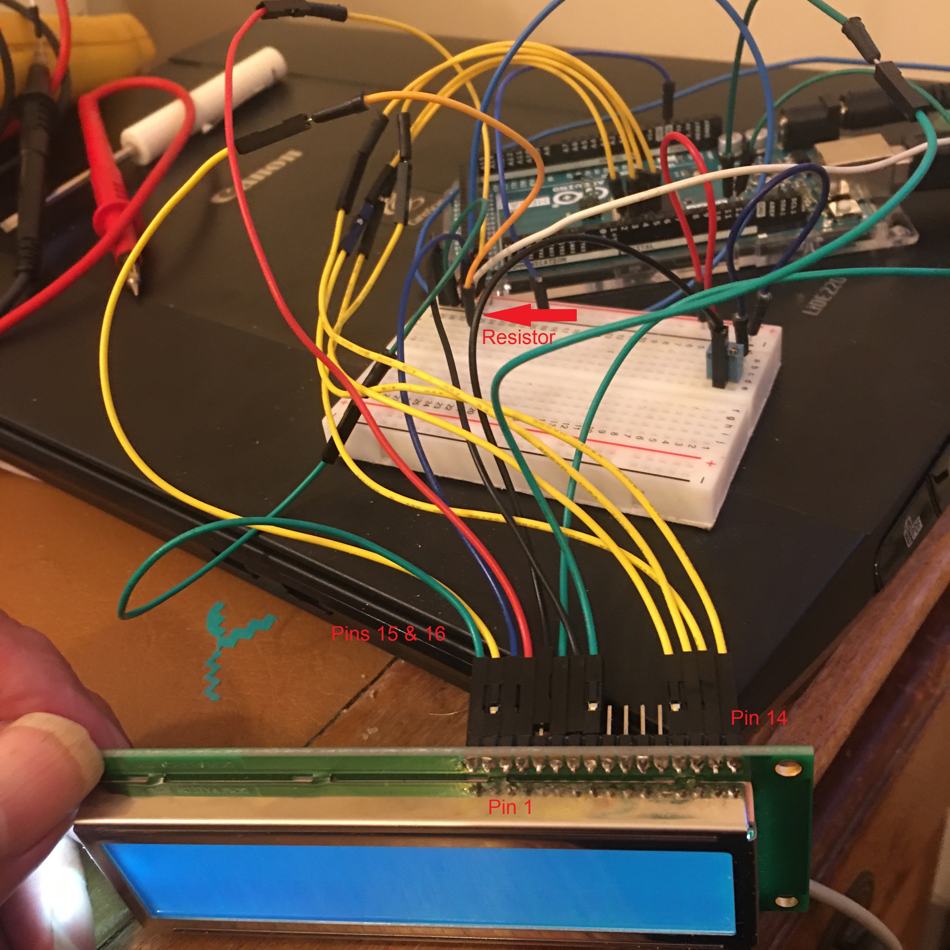
in desperation I have stripped out all surplus wiring from the circuit leaving the bare minimum. Still no luck display does not work.
Photograph of circuit attached.
any help gratefully received
regards
LesC
Seriously, you could plug the display straight into the breadboard.
Then you just have 8 male-male jumpers to the Arduino headers.
pull the breadboard and Arduino to straighten the jumper wires.
the photo would be very clear. we could identify individual wires.
you were successful in #11. Even though you had an atrocious rats nest.
Wire it neatly. You will spot errors. Or readers' eyes spot errors.
If the wiring is verified but you get no display, chuck it. Buy another one.
David.
I believe I know the issue at fault here,
It may be a late answer and no longer relevant but I thought id pass on the solution for other users like myself who struggled with this issue.
I too was connecting an arduino to a displaytech 162F LCD and found that I was able to make the appropriate connections and power up the screen so that it lit up but that I could not get any text to display (not even "Hello World"). I checked the wiring multiple times but could not find any issues.
I finally determined the error was that the contrast on the screen (set by the potentiometer) was so high that I couldn't actually see the text appearing on the screen even though it was.
The fix is to reduce/increase the potentiometer resistance split until the text is visible.
Hope this helps someone in the future