Hey guys
We are afraid of signal being chattered between 1.x ~ 2.x V. We use Arduino Mega 2560 R3 board. Do we need to place any extra schmitt trigger before the signal goes into the board ?
Thank you
Hey guys
We are afraid of signal being chattered between 1.x ~ 2.x V. We use Arduino Mega 2560 R3 board. Do we need to place any extra schmitt trigger before the signal goes into the board ?
Thank you
Read the data sheet.
I did in arduino.cc there was no mentioning about it. But there was one in Atmel data sheet about 2560 chip so i am confusing
An input level below VIL will be interpreted as a logic 0, anything above VIH will be interpreted as a logic 1.
In between is grey area and should be prevented.
If you take a look at ATmega2560 datasheet, 13.2 Ports as General Digital I/O, Schmitt trigger is there on input. However, I am not so sure about its functionality in real.
Things like push buttons need "debouncing". People often use SW to remove flickering at raise and fall edge of pulse. No external parts are needed.
Personally, I prefer to use an external Schmitt triggers on input. It helps also with slow transition beside with noisy one.
Not necessarily, if the dead zone around Vcc/2 fits.
In some older data sheets the Y axis had a wrong scale indicating almost no hysteresis (mV). This error should be fixed now.
Then it's not a logic level signal and a schmitt will not help.
Sounds like you have a noise/grounding problem that needs to be corrected.
What is the source of this signal?
What are the minimum and maximum voltge levels of this signal?
Yes to prevent the grey area we wonder if extra schmitt trigger is necessary 
thank u for answering
Is it a logic level digital signal?
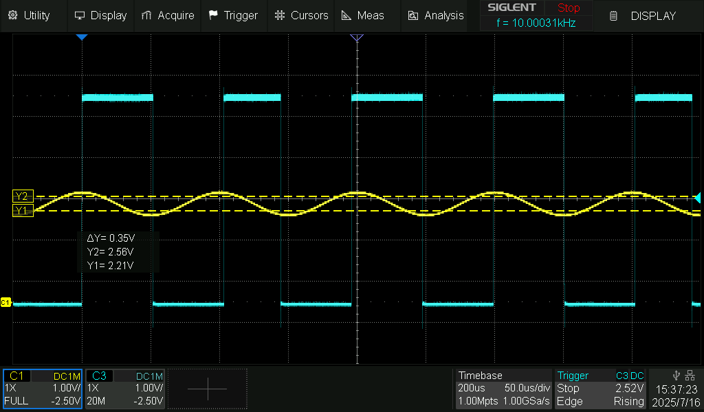
I've done a test to demonstrate how a Mega 2560 input performs.
Using the following code, which continuously reads digital input pin and sets an output pin to the same state.
I applied a 1Hz sinewave from a function generator to the input and monitored the input and output.
const byte inputPin = 7;
const byte outputPin = 12;

void setup() {
  pinMode(inputPin, INPUT);
  pinMode(outputPin, OUTPUT);
  }

  void loop() {
  digitalWrite(outputPin, (digitalRead(inputPin)));
}
Here is an oscilloscope trace showing the results:
This is showing the input changing from low to high at 2.56V and from high to low at 2.21V.
For your particular board.
and a particular chip temperature.
So it shows hysteresis is built in.
and at a particular supply voltage from a particular USB port.
If you're already playing with it, try a higher frequency.
Here is a higher frequency and lower amplitude sine wave:
Frequency 10kHz, amplitude 0.55V (going from upper threshold +100mV to lower threshold -100mV).
I've left the cursors in the same position.
There is a phase difference between the two signals.
This is because the time that it takes to do a digitalRead(), a digitalWrite() and go around loop() becomes more significant at a higher frequency.
This makes it look as though the thresholds are different.
Even with a nice 5V amplitude square wave input, there is typically 5µs to 15µs delay before the output changes.
Yes. These functions are quite complex. It is for Arduino purposes. With the direct port manipulation it would be faster.
Anyway, we can say the built-in Schmitt trigger works even if 10kHz is not too much. I hope there is no hidden switching noise on edges. It doesn't seem to.
You picked just one of the mislabeld diagrams that claims a hysteresis of less rhan 1 mV.
Please find out that this diagram claims a hysteresis of 0.35mV!
In the ATmega 48 to 328 data sheet the various Pin Input Hysteresis diagrams show mV or V, depending on the controller. Here it's incredible that inside a chip family a parameter varies by a factor of 1000. Also it were very hard to measure or make use of a hysteresis of 0.5 mV.
You are right. You see only what yuo want to see, I wanted to see 0.35V
Typical switch points are 0.3 and 0.6 * VCC.
That translates to 1.5volt and 3volt if VCC is 5.0volt
So the pin might never go HIGH with less than 3volt.
An analogue input can be used if speed is not a priority.
Then you can set the pin to any on/off threshold you like.
Leo..