After reading the documentation, I don't know how to handle the code...
it's not a usual 4-digit display with CLK DIO VCC GND pins but with GND SCK SDI RX 5V pins and I don't know how to program it.
Could somebody help me ?
Cheers
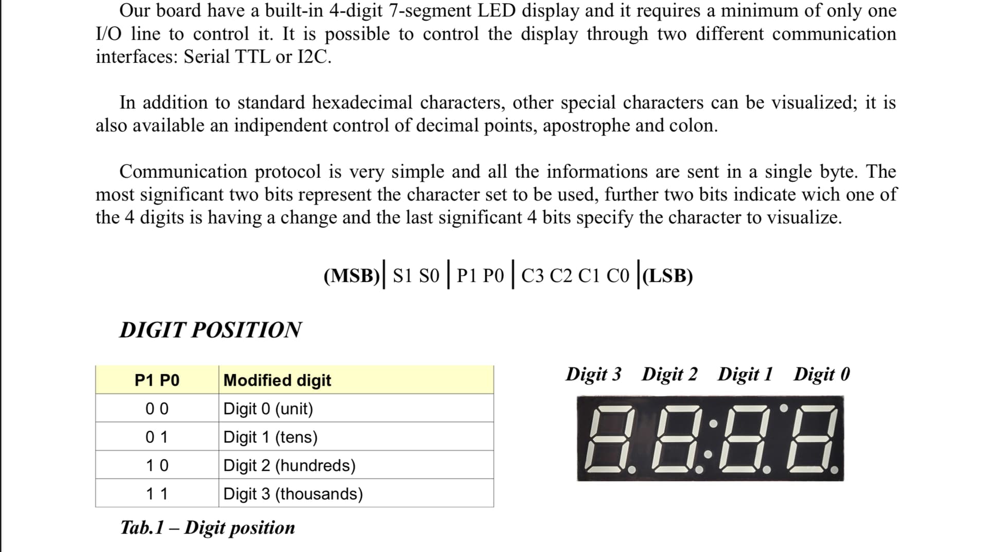
The wire coming from the back seems to be connected to pin 1 of the UNO which is the Serial Tx pin, likely connected to the Rx pin. So sending the byte is just a matter of a Serial.write(). The other 2 wires are likely 5V and GND. They did not use the I2C pins.
I believe they would use likely 115200 bauds as it would make sense to not go too slow but it might be 9600 or autobaudibg maybe ?
So if you wire as they did and run this
void setup() {
  Serial.begin(115200); // 115200 bauds - try 9600 if it does not work
  Serial.write(0x79); // -
  Serial.write(0x23); // 3
  Serial.write(0x82); // .
  Serial.write(0x11); // 1
  Serial.write(0x04); // 4
}

void loop() {}
You should see as they say in the doc -3.14
If not try to change the baud rate to 9600
May be a small delay() is needed if the module is slow to boot up.
I would configure it as I2C, that requires 4 wires, power, ground, SCL, and SDA.
Operating voltage +5V
Power current
1.2mA typ. (with all LEDs off) 80mA (with all LEDs on)
Interface I2C, Serial TTL
I2C address 0x0C
When you get it connected use the I2C scanner to verify it is at address ox0C. Read the documentation for the wire.h library, from that you should be able to communicate with it.
Of course this could be wrapped into a function but I find the Serial interface more straightforward (and a bit faster at 115200 bauds than I2C default 100kHz)