Hello!
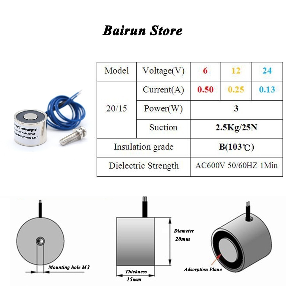
I will be using arduino nano to turn on and off 5 electromagnets like these ( https://www.aliexpress.com/item/32815809960.html?spm=a2g0o.placeorder.0.0.4b38321eMh4iBq&mp=1 ). The magnets will be powered with external powersupply.
At first I thought about using a relay board but I understand that its not the best solution because it wont be able to switch as fast and im not using mains voltage. By reading other posts I saw a solution with logic level power MOSFET and another guide with ULN2803: 8 Channel Darlington Driver ULN2803A.pdf (377.5 KB)
Any suggestions of what might be the best solution, because my knowledge is quite limited and I just dont want to fry the whole arduino.
Am I correct, that MOSFET solution would need a flyback diode and a pull down resistor?
Does the darlington driver even work for my solution and wouldn`t it need flyback diode and pull down resistor too?
The solenoid draws 0.25A at 12V and the ULN2803A driver can handle 0.5A at up to 50V. The ULN2803A also has built-in snubber/flyback diodes. I think the ULN2803A will work without any additional parts.
Thank you! I wanted to go with the ULN2803A too, but now I`m not sure how to wire it correctly.
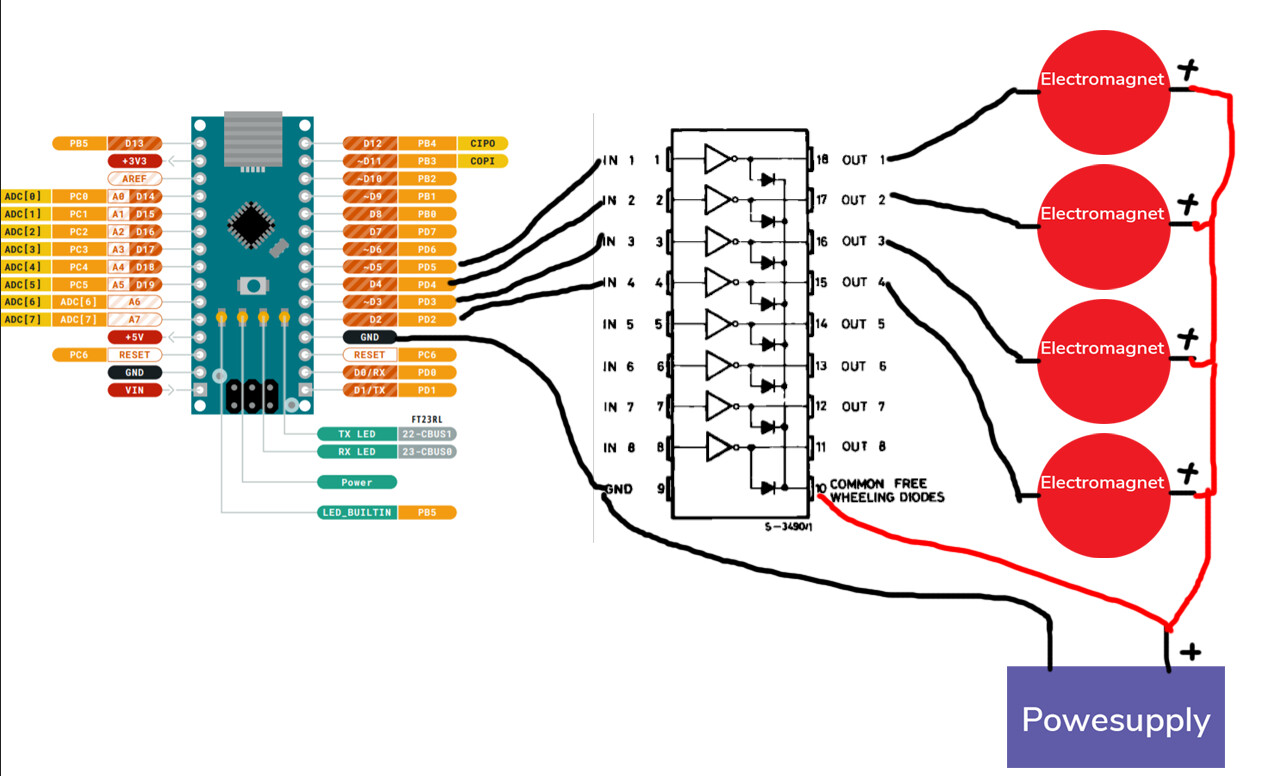
I have arduino nano, 5 electromagnets, external 12v powersupply and ULN2803A driver. Here is the pinout for the driver:
Am I correct that I connect arduino outputs to input pins of the driver and output of the driver goes to the electromagnets; to common goes 12v powersupply? Does GND connect to arduino or powersupply?
Yes. Remember that the + side of the electromagnet goes directly to the +12V power and the - side goes to a driver output. The 'COMMON' pin is just to put a diode across each output.
Both. Arduino Ground and Power Ground should connect together.
You connect it to +12V which is also connected to the + side of all of the electromagnets. If you don't connect it then the built-in flyback diodes are not connected across each output.
I do not know about the frequency. I was thinking to determine that by trial and error when I
build the circuit.
I will be using those magnets to control and move ferrofluid in a bottle. Just using it as a cool visual display and possibly will add joystick controls too
At 250mA Vces is 1.2V; if all 5 electromagnets are on you have 1.2V * (5*0.25A) = 1.5W
that is pushing the power dissipation for the chip.
You could glue on a small heat sink.
If you used the 24 V version of the electromagnets (with appropriate supply of course), a TPIC6B595 would control them all perfectly using only three Arduino pins.
Thank you for this information, didnt even think about that. I dont think I will run them all together much, but I will definitely check that it doesn`t overheat.
That is indeed cool to use a shift register, but Im not sure I want to make it more complicated for me, because I just only found out what it is
But why would I need to use 24v electromagnets for this?
Actually makes the code somewhat simpler in many ways! And uses fewer Arduino pins. Using the shift register, you can put the individual controls for each electromagnet as bits in a byte variable, and write them into the shift register so that they all update simultaneously.
They use less current, so are within the capability of the TPIC6B595 which then runs cooler than a ULN2x03.
("ULN2x03" means either a ULN2803 which controls 8 outputs, or a ULN2003 which controls 7.)
Although the ULN2803A can drive 500mA per pin, the total current the chip can drive is (I recall) 2.5amp. Driving 5 coils would hit the total current limit of the driver.
And when energising a coils, you often get an initial current surge, so for frequent switching of 5 coils you might have an overheat (or fried chip) problem. Maybe not immediately.
Maybe split the load over two driver chips.
News to us! - thinking of filament bulbs or motors or transformers perhaps? Coils have the exact opposite, the current builds up gradually when energized due to the back-EMF - its switch-off that's the issue you have to deal with where a destructive voltage surge is generated if not snubbed or prevented (free-wheel diodes are commonly used for this in DC circuits)