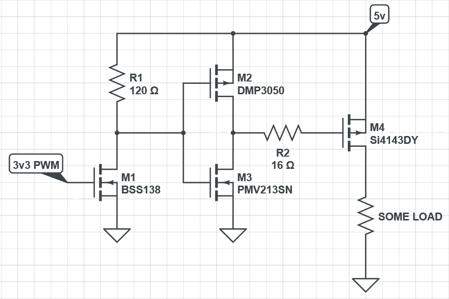
I would like to drive a p channel mosfet, since i could not find a suitable driver for my application on the store i am selling, i am kinda forced to make my own pmos driver . Im hoping that you guys can check my work if there are problems in my circuit or component selection
The PMOS i am using is a SI4143DY. I have learned that a MOSFET must be driven by low impedance and the best way i could think of doing that is by a totem pole circuit NSS40301 and NSS40300(Sorry cant hyperlink the datasheet the forum limited me to 2 links). The maximum freuency i want to switch at is 1MHZ. I am also using a bss138 nmos as a level shift instead of an NPN so that i can eliminate the gate resistor.
A driver chip has often a number of tricks to allow a large current for the gate capacitor.
The mosfet is not for high frequencies with its gate capacitance of 6nF. A lot of energy will be wasted at 1MHz to deal with that capacitance. The rise and fall times and the delays in the datasheet are with a very strong signal.
At 1MHz the gate resistance is 2.3 Ω, that is what you are dealing with at 1MHz.
The BSS138 gets to much current at 24V with 50 Ω.
I suppose that the output should not be active when there is no PWM signal. That means the gate must be high, and Q1 must be off. However, it is turned on with R4. I think that R4 needs to be 10k to GND.
The two transistors is a safe way to amplify a digital signal. The output signal will be 1.2V lower, even up to 2V according to the datasheet.
when i did my first order calculations i got
T= Q/I = 81nC / 1.5A
T = 54ns == 108ns (rise and fall) is about 10MHz well above my need,
But thats what i think i could be entirely wrong about something. Am i missing something?
I forgot to change the value, it should be 120 ohms since the bss138 can only handle 200mA of current.
I see my mistake , and actually i agree with you now that i checked again. An "OFF" PMOS have a gate voltage of the same as Source, to do that the bss138 must be OFF. an OFF bss138 there must be a pull down.
are you saying that transistor selection is inadequate? can you tell the transistor specs i need fo
Probably not, but the combination of that gate resistance and the 1MHz and the 6nF just feels problematic. All that energy has to go somewhere, so you have to check the temperature of the components.
No, its good and the circuit is inherit safe. Just keep in mind that the output signal can be 2V less top-to-top.
Now that I think about it, the emitter side is slower than the collector side.
Do you have a good oscilloscope to measure the signal at the gate ?
If the power mosfet gets hot, then you know that there are slow slopes.
Although i dont personally own one, i can always borrow at my university.
This worries me what do you mean 2v less >? Im worried that at my lowest source voltage (5v) i might not turn it adequatly on, 3v might still be off for this mosfet.
My target frequency is still negotiable, the pressing issue would be mosfet not turning fully ON it might overwhelm the tiny heatsink i will place on it
Can you tell more about your project ? Why do you want to switch a mosfet at 1 MHz ?
There are a few versions of the NSS40300 / NSS40301 transistors. The "MZ", "CT", "DD" and "MD".
Manufacturer's page of the "CT": https://www.onsemi.com/products/discretes-drivers/general-purpose-and-low-vcesat-transistors/nsvs40300ct with datasheet.
Its VBE(sat) is maximum 1.0V. Also the Figure 7 shows that at 40°C it is near 1.0V.
Since both transistors have that, the output at the emitters can be 2.0V lower (top-to-top) than the power supply. That is the price that you pay for a circuit that is inherit safe.
The mosfet has a lower RDS(on) with a gate voltage of 10V. With a power supply of 5V, it should work for a load of a few amps.
Im going to use them to drive LEDs, you might say use a N channel instead but i just want to play with P channel Mosfets hehe . Im not sure if 10A still falls in "few". I already tried to do tthe math on temps and i should be fine.
Oh no looks like i have to go transistor hunting again. I have to look for a transistor that has a Vbe sat of 0.5v.
Can replace Q3 with a Schottky diode (Q1 can pull the gate to ground via that diode).
Then Q1 must be able to handle the gate current + pull down current, so not a BSS138.
I would rather use a gate driver chip.
Then you should use constant current switching LED drivers (with inductors), not P-channel fets.
Unless you're talking about LED strips.
Where did you get the 1Mhz from.
Note that switch frequencies need to x-bit higher than the base dim frequency.
If you're thinking of a 1Mhz dim frequency and 12-bit dimming, then switch frequency must be 4Ghz.
Leo..
as i mentioned ill be driving LEDs, LED strips to be precise. 5v, 12v, and 24v version the 5v version dont need to be DIMMED so their switch frequency would be <1Hz. 12v and 24v on the other hand will be dimmed via PWM, i have read articles that switching above the aduio frequency is best. so my targert is 100kHz frequency PWM, 100 dimming levels is fine with me so atleast 1MHz switch frequency on the PMOS, I would really like to make only 1 board for the 3 voltage source needed.
I have been looking into complementary components where they are packaged in 1 IC, is shoot through still a problem for those components
I already told you that PWM dimming is a trade-off between PWM frequency and resolution.
If you choose 100kHz, then you might only have five equal dim steps, not 100.
Leo..
I have to disagree with you since it has already been done, the zero can achieve 250Khz freuquency at 6bit resolution (63 steps) even at 63 steps ill be fine with it, and if we go by what you said at half that frequency the step would only increase