Driving RGB leds with the ULN2003A and pwm on the attiny85 [SOLVED]

Hi,

I have a simple project that drives one 5mm common cathode RGB LED.
Now I want to scale it to a group of 9 leds.
There are a lot of schematics showing how to do this with mosfets and/or simple transistors, but all I have right now are a few ULN2003A ICs.
It looks that they are mostly used to drive 7 segments leds or motors, the only schematic I was able to find showed a configuration with a common anode led.

However, all the RGB leds I have are common cathode.
I don't know how to connect them to the ULN2003A
If I connect them like this

Where do I connect the +5V ? To pin 9 ???

thanks!

'2003 outputs sink current, not compatible with common cathode.

That's what I was suspecting, but from the datasheet's fig 22 I thought that I might be wrong.
Can you tell me what IC I would use for this application with common cathode leds ?
thanks!

Equally inefficient and antiquated, the UDN2981 / MIC2981

Will the 9 rgb leds show the same colour or different colours?

If same colour, it might cost less to change your leds. 12V rgb led strips are common anode. You could cut a 9 led length from a strip and wire that to your uln2003.

For different colours on the 9 leds, maybe ws2812 leds would be easier.

Thanks.
I don't know enough to know that sort of things, I'm at the level of "join part A to part B" (and hope it don't go BANG! :slight_smile:
But I may as well ask what's the better way to drive this modest load. I'm talking about 9 5mm RGB leds all with the same color. I understand (now) that common anode are better for this kind of thing (I'll get to the why one of these days) but all I have right now are trivial 5 mm common cathode.

thanks!

PaulRB:
Will the 9 rgb leds show the same colour or different colours?
If same colour, it might cost less to change your leds. 12V rgb led strips are common anode. You could cut a 9 led length from a strip and wire that to your uln2003.
For different colours on the 9 leds, maybe ws2812 leds would be easier.

I want to build a type of flashlight that produces a preset group of colors. A strip would be ok for something diffuse like a mood light but I want some level of focus, I'll be taking a metalized plastic reflector from a cheap Chinese 9 led flashlight (I'd love to be able to buy that reflectors alone but so far had no luck finding them).
Probably this would be much better done with a single higher power rgb led, maybe something like these, but at my knowledge level I think I'd better keep to the low power stuff.

OK then. You just need 3 PNP transistors, like bc327. Just put 1K resistors between the transistor bases and the Arduino PWM pins. You will still need 27 series resistors.

Would it be something like this ?

thanks!

Yes that's it.

Note that because these are PNP rather than NPN transistors, a HIGH output from the Arduino pin switches them off and LOW switches them on. So analogWrite(pin, 0) is full brightness and analogWrite(pin, 255) is off.

Hi again.

I implemented this circuit using 3 BC327-40 with 1k resistors to the base and it works ok, I'm driving 6 RGB leds without problem.
The only snag is that rgb(0,0,0) (the 3 pwm attiny85 solution I'm using already inverts the pwm value) is not black, I have always some light on red and green (but not on blue). I didn't had this problem when driving only one led without the transistors.
Apart from the leds I do have a button with simple RC debouncing.
I'm powering the bread board with a small bread board power supply from 12v. This power supply is rated <700mA so with 6 leds I'm well inside the range.
Could this be be an implementation problem, or something caused by a cheap bread board ?
I already tried to shunt the top and bottom power rails but makes no difference.

I'm using an attiny85 @ 8MHz (internal), the pwm config is as follows:

  pinMode(0, OUTPUT);
  pinMode(1, OUTPUT);
  pinMode(4, OUTPUT);
  TCCR0A = 3<<COM0A0 | 3<<COM0B0 | 3<<WGM00;
  TCCR0B = 0<<WGM02 | 3<<CS00;
  GTCCR = 1<<PWM1B | 3<<COM1B0;
  TCCR1 = 3<<COM1A0 | 7<<CS10;

Do you have any suggestion ?

thanks.

Try 10K pullup resistors on the Arduino pins driving the transistor bases.It sound like the pnp are not switching fully off.

Post your whole sketch. Some comments on lines like those you posted about would be useful.

Hi Paul,

Thanks for your reply, I tried 10K on the base of the red and green transistors but it made no difference whatsoever.
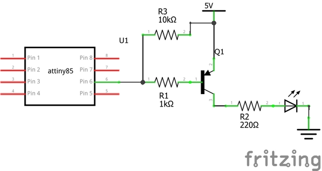
Here's the cricuit

And here's the sketch

#define F_CPU 8000000UL
#include <avr/io.h>
#include <util/delay.h>

// 2017.04.09
//    inverter a função de output, os leds com os transistores PNP são invertidos
//    portanto o reverse pwm fica direito.

/*
    N/C     PB5 [1]-\/-[8] GND
    N/C     PB3 [2]    [7] PB2 -> BUTTON
    BLUE <- PB4 [3]    [6] PB1 -> GREEN
    vcc         [4]____[5] PB0 -> RED 
*/

// ATtiny85 outputs
const int Red = 0;
const int Green = 1;
const int Blue = 2;
volatile uint8_t* Port[] = {&OCR0A, &OCR0B, &OCR1B};
int Pin[] = {0, 1, 4};


byte C=1, lastC=1;
unsigned long lastPress=0UL;
unsigned long lastChange=0UL;
//unsigned long autoChangeDelay=180000UL; // 3*60*1000 - 3 minutos
unsigned long autoChangeDelay=30000UL;


const byte cor[9][3]={
  { 0, 0, 0 },      // off
  { 255, 0, 0 },    // vermelho
  { 255, 4, 0 },    // laranja
  { 255, 20, 0 },   // amarelo
  { 0, 255, 0 },    // verde
  { 0, 0, 255 },    // azul
  { 34, 0, 64 },    // indigo
  { 139, 0, 100 },  // violeta
  { 255, 255, 255}  // branco
};

// 3 PWM code from http://www.technoblogy.com/show?LE0
void setup() {
  pinMode(Pin[Red], OUTPUT);
  pinMode(Pin[Green], OUTPUT);
  pinMode(Pin[Blue], OUTPUT);
  pinMode(SW,INPUT);
  // Configure counter/timer0 for fast PWM on PB0 and PB1
  TCCR0A = 3<<COM0A0 | 3<<COM0B0 | 3<<WGM00;
  TCCR0B = 0<<WGM02 | 3<<CS00; // Optional; already set
  // Configure counter/timer1 for fast PWM on PB4
  GTCCR = 1<<PWM1B | 3<<COM1B0;
  TCCR1 = 3<<COM1A0 | 7<<CS10;

  rgb(50,0,0);
  _delay_ms(5000);
  rgb(0,0,0);

  attachInterrupt(0, nextColor, FALLING);
}

// if button was pressed set C to the next color
void nextColor()
{
  unsigned long now;

  now=millis();
  if(now<(lastPress+1000UL)) return;
  lastPress=now;
  C++;
  if(C>8) C=0;
}

void loop() {
  unsigned long X;

  X=millis();

  if(C!=lastC && X>(lastChange+500UL))
  {
    lastC=C;
    rgb(cor[C][0], cor[C][1], cor[C][2]);
    lastChange=X;
  }
  if(X>(lastChange+autoChangeDelay))
  {
    C++;
    if(C>8) C=0;
    lastChange=millis();
  }

}

// Sets colour Red=0 Green=1 Blue=2 to specified intensity 0 (off) to 255 (max)
void SetColour (int colour, int intensity) {
//  *Port[colour] = 255 - intensity;
  *Port[colour] = intensity; // com os transistores PNP é invertido
  
}

void rgb(int rr, int gg, int bb)
{
  SetColour(Red, rr);
  SetColour(Green, gg);
  SetColour(Blue, bb);
}

I tried 10K on the base of the red and green transistors

That's not what I said at all. Please read my post again more carefully. If you don't understand the term "pull-up resistor", please ask. I did not say to remove the 1K base resistors.

Sorry, I totally misunderstood.
I don't have problems admitting my ignorance but here I failed to notice that I didn't knew.

Is this it ?

thanks

Yes, that's better. Tried it yet?

If that does not fix the problem, can you try the standard blink sketch? Do the leds go fully out with that sketch?

Hi,

Well, it did not work.

The 1st thing I tried was reburn the bootloader setting the fuses to 1MHz internal clock.
There is some text in the page where I got the 3 PWM config that said that the author was setting the clock to 1 MHz. But no, no difference at all.

I made a basic blink sketch using digitalWrite, without any PWM config.
And it works ok, digitalWrite(pin,HIGH) turns the leds off, LOW turn them on, as you said it should do.

I think that this proves that it is not a circuit problem, it's an attiny problem.

I'm going to write the same blink sketch but using PWM.
If I got the same problem I'm going to finish my project with a Nano and implement it with a pro Mini, when I got a few mosfets and/or common anode leds I will try again.
I don't want to drop the attiny, there's something in making a bare IC do something that I find more fun than just program an Arduino, silly I know, but I'm in this for the fun.

Thanks for helping me.

#define RED 0
#define GREEN 1
#define BLUE 4

// note: with the pnp transistors
// LOW is ON and HIGH is OFF

void off();
void on();
void blink(int, int, long);

void setup() {
  pinMode(RED, OUTPUT);
  pinMode(GREEN, OUTPUT);
  pinMode(BLUE, OUTPUT);
  on();
  off();
  delay(5000);

}

void loop() {
  blink(RED,10,1000L);
  blink(GREEN, 10, 1000L);
  blink(BLUE, 10, 1000L);
  off();
  delay(1000);
}

void on()
{
  digitalWrite(RED, LOW);
  digitalWrite(GREEN, LOW);
  digitalWrite(BLUE, LOW);
  delay(100);  
}

void off()
{
  digitalWrite(RED, HIGH);
  digitalWrite(GREEN, HIGH);
  digitalWrite(BLUE, HIGH);
  delay(100);  
}


void blink(int pin, int times, long t)
{
  int f;
  for(f=0;f<times;f++)
  {
    digitalWrite(pin,LOW);
    delay(t);
    digitalWrite(pin,HIGH);
    delay(t);
  }
  off();
}

Yup.
It's an attiny problem. When using PWM the red and green leds do not turn totally off.

#define F_CPU 1000000UL
#include <avr/io.h>
#include <util/delay.h>

#define RED 0
#define GREEN 1
#define BLUE 4

// ATtiny85 outputs
const int Red = 0;
const int Green = 1;
const int Blue = 2;
volatile uint8_t* Port[] = {&OCR0A, &OCR0B, &OCR1B};
int Pin[] = {0, 1, 4};

void off();
void on();
void blink(int, int, long);
void SetColour (int, int);
void rgb(int, int, int);

void setup() {
  pinMode(RED, OUTPUT);
  pinMode(GREEN, OUTPUT);
  pinMode(BLUE, OUTPUT);
  // 3 PWM code from http://www.technoblogy.com/show?LE0
  // Configure counter/timer0 for fast PWM on PB0 and PB1
  TCCR0A = 3<<COM0A0 | 3<<COM0B0 | 3<<WGM00;
  TCCR0B = 0<<WGM02 | 3<<CS00; // Optional; already set
  // Configure counter/timer1 for fast PWM on PB4
  GTCCR = 1<<PWM1B | 3<<COM1B0;
  TCCR1 = 3<<COM1A0 | 7<<CS10;

  on();
  off();
  _delay_ms(5000);

}

void loop() {
  blink(Red,10,1000L);
  blink(Green, 10, 1000L);
  blink(Blue, 10, 1000L);
  off();
  _delay_ms(1000);
}

void on()
{
  rgb(255,255,255);
  _delay_ms(100);  
}

void off()
{
  rgb(0,0,0);
  _delay_ms(100);  
}


void blink(int col, int times, long t)
{
  int f;
  for(f=0;f<times;f++)
  {
    SetColour(col,255);
    _delay_ms(t);
    SetColour(col,0);
    _delay_ms(t);
  }
  off();
}

// Sets colour Red=0 Green=1 Blue=2 to specified intensity 0 (off) to 255 (max)
void SetColour (int colour, int intensity) {
//  *Port[colour] = 255 - intensity;
  *Port[colour] = intensity; // com os transistores PNP é invertido
  
}

void rgb(int rr, int gg, int bb)
{
  SetColour(Red, rr);
  SetColour(Green, gg);
  SetColour(Blue, bb);
}

Why not change your code so that when the pwm value is the value for off (0 or 255, can't remember which) the code does a digitalWrite() instead? A little ugly, but you get to keep using the tiny.

What tiny core are you using?

I prefer this one. It is actively maintained and is author is a regular contributer to this forum and very helpful (DrAzzy). It may support 3 pwm pins using the normal analogWrite() rather than having to write to avr registers like your code above does. Might be worth trying to see if it suffers from the same problem or not.

I almost tried that last night decided against in the bases that I didn't know what it could happen.

Well, I tried it. It does not work, at least not as I want. At first I was just doing a digitalWrite(pin, LOW) if the value was below 2. At 1st I thought that the program crashed, it set the RED led to on and stayed there (it should be off).
But it looks that it is not a crash after all, Instead of doing the digitalWrite if value <2 else do the pwm stuff, now I'm doing the digitalWrite LOW if value <2 but then continue to execute the pwm code.
And I can see it is not crashed, I don't know what it is doing but it's doing something, I'm getting blue+red most of the time and then blink red alone, no green, at the moment I don't see how my blink program could be doing that but I'm going to investigate further.
I wish I had a debugger to see what it's doing and an oscilloscope (witch I don't know how to use anyway) to see what's coming out of that pins. Atmel Studio looks to have some kind of debug mode but it's a bit too heavy for my machine.

I'm using the core from https://raw.githubusercontent.com/damellis/attiny/ide-1.6.x-boards-manager/package_damellis_attiny_index.json witch probably is the one at GitHub - damellis/attiny: ATtiny microcontroller support for the Arduino IDE

I'm going to try the one you suggest.

thanks.