Hello everybody,
I have a small solar panel with the following specs:
Output Voltage: 6V/DC
Output Current: 150mA
Power: 0.9W
I am trying to connect it to an Arduino Mega in order to measure the voltage, the current and the generated power because I want to log these data. I don't want to power the arduino with the solar panel, I'm using usb to do that.
Since I'm not very familiar with electronics, I'm asking which is the easiest way to connect the solar panel to the arduino to measure the mentioned values. It would be great if it is possible to use only resistors for that.
Schematics are really appreciated!!
Do you expect the solar panel to be powering anything and if so, what?
If you just want to estimate the total amount of power (say, per day) that the panel can generate under some given set of circumstances, then that can be done by an Arduino and two resistors. We need to know more to suggest a strategy.
No, I don't want to power anything with it. As you said, I'm interested only in the measurement of the power.
Can you please describe better how I should use two resistors?
If it is not powering anything, you won't be able to measure power!
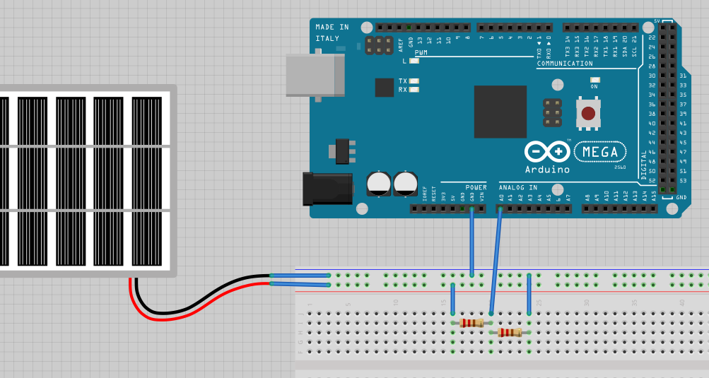
Connect the two resistors in series. Connect an analog input to the top resistor and another at the junction between them. The solar cell also connects to the top one and ground.
You need two resistors so you can monitor current. Measuring the voltage at the top of the two resistors to get the output voltage of the cell. measure the voltage between the resistors to get a value that can be divided by the lower resistor value to get the current. The sum of the two resistors is the load on the cell. The power is the voltage measurement * the current measurement.
alessandro_montanari:
Can the 6V from the solar panel damage the Arduino somehow?
Yes.
You need to put two equal resistors in series from the panel output to ground. Measure the voltage at the center pint between them, it will be half the panel voltage.
The values aren't critical,try 5k. Lower values mean lower noise in the reading but you'll be shunting more electrons away from your panel.
Measuring current is harder. You could put a small resistor in series with the circuit (between device and ground) and measure the voltage drop across it. The value will depend on the accuracy you need and how many volts you can afford to drop in the resistor. Use Ohms law with 150mA as the current...that's your maximum value.
.
Assuming the Arduino does not draw any current, which is a good assumption, why does he need another "small resistor to ground"? The center connection of any voltage divider will do fine as long as you know the value of the resistor.
For example, if he has two one hundred ohm resistors and the solar cell is putting out 6v:
The voltage at the center junction will be 3 volts, which we multiply by two to get the 6 V solar cell voltage, and divide by 100 to get a current of 30 mA. The power will be the 6 V * .03 A or .18 W, which is also the 6 V squared divided by 200.
KeithRB:
The voltage at the center junction will be 3 volts, which we multiply by two to get the 6 V solar cell voltage, and divide by 100 to get a current of 30 mA. The power will be the 6 V * .03 A or .18 W, which is also the 6 V squared divided by 200.
You're not measuring what the panel is capable of. The resistors are limiting the current.
What precisely are you trying to measure?
The output power of a solar panel varies depending on a large number of variables.
Primarily the solar radiation intensity , which changes over the course of the day, and whatever the solar panel is connected too.
Fixed value resistors will provide some data , but it wont mean much , as the values have to be changed depending on the level of light intensity.
To accurately measure how much power the solar panel can deliver over a period of time , needs a MPPT (Maximum Peak Power Tracker) which is an electronic device that continuously adjusts the apparent load to match the solar panels peak power point , and a battery to absorb the energy.
You could use a resistor instead of the battery if you dont care what happens to the Solar panels output.
You can make a MPPT charger with an Arduino if you wish.
Heres an article on how to do so. http://www.timnolan.com/?page=arduino-ppt-solar-charger
What I had in mind were two resistors that would load the panel at what might be (given the meager product description) the maximum power point of the panel in full sun. Assuming the MPP is 0.9 watts at 6V then the total load resistance to match that would be V^2/P = 40 ohms.
Two 22 ohm resistors in series would probably be OK. If you monitor the voltage Vj from the junction of the two resistors to ground (as suggested above) you can calculate the instantaneous power across the load, which is 2Vj*I = 2Vj2/22. Example: suppose Vj = 3 V, then the instantaneous power is 0.82 watts.
That would get you started. However as the previous poster suggested, to get the optimum power you need a "maximum power point tracker" load and also to continuously reorient the panel during the day so that is perpendicular to the sun's rays.
Thanks everybody for the answers!!
I'll try to summarize.
Since I want only to do experiments on the solar panel/arduino and I'm not interested in a very accurate system connecting everything as shown in the picture in the attachment should be fine, right?
I was thinking to use two 100ohm resistors and then I can compute the following things:
Voltage = * 2
Current = / 100
Power = Voltage * Current
Is this correct? Will the current be too high for the arduino?