Hi Everyone
I am new at this.
I done a electric gate system and code that work well with limit switches, infrared obstruction detection and button C to pause gate untill you want the motor to continue.
The only problem I got is that the motor start very fast and stop very fast.
I tried to use the PWM control with int EN1pin = 7: int EN2pin =8: and ENApin = 9; and I set the motor speed to start at 70 and go up to 255 and then from 255 back down to 70. the following to start motor in void loop.
'for (motorSpeed = 70; motorSpeed <= 255; motorSpeed++) {//--------Open At Variable Speed Up
analogWrite(ENApin, motorSpeed);//------------------Enable Command
delay(100);//---------------Time It Take To Speed Up Hiher Number Is Slower
}
for (motorSpeed = 255; motorSpeed >= 70; motorSpeed--) {//---------- Open At Variable Speed Down
analogWrite(ENApin, motorSpeed);//-----------------Enable Command
delay(100);//-----------------Time It Take To Speed Up Hiher Number Is Slower'
The motor start slow and speed up and then he speed reduces but the only problem is the motor work but then my limit switches , Infrared obstruction sensor and all the other controls stop working.
I think it is because of the 'for' command I tried everything I know but cant get everything to work together.
Can someone please help?
regards
Johannes
While you are in the for loop, none of your other code is being executed. Have the last statement of setup stat the motor at the slowest speed. In the loop, at the bottom, increase the speed, check for max speed, if true, set speed to slowest again.
Can you please post a copy of your circuit, a picture of a hand drawn circuit in jpg, png?
Hand drawn and photographed is perfectly acceptable.
Please include ALL hardware, power supplies, component names and pin labels.
Hi
The driver is XY-160D 7A/160W dual DC motor drive module high power industrial level positive and negative PWM speed regulation L298 logic
and the details I found for the motor is
At any rate an average wiper draws 5 amps, rising to 10 to 12 amps under heavy/stall load. Supposing the motor efficiency is 60% then the total power maxes out around 4 x 10 x 12 watts = 480 watts input and 0.6 x 480 watts output power
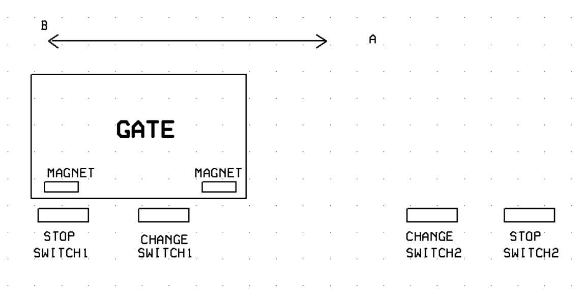
From the position shown, to OPEN, STOP SWITCH1 is active, the gate moves SLOWLY to the first CHANGE SWITCH1 and activates it, where it goes to HIGH speed.
When it activeates the CHANGE SWITCH2 the speed drops to SLOW and when it activates STOP SWITCH2 the gate stops.
A similar procedure when you open the gate.
The gate that at my workplace has an encoder on the gate and just two limit switches.
To set it up, it does a very slow open and close to LEARN where the ends of the gate travel are.
Then in normal operation using the encoder it has full control over acceleration and deceleration.
Hi, @lappieslatandra
Sorry mate but the diagram does not have the resolution to read pin numbers etc.
Can you PLEASE post a copy of your circuit, a picture of a hand drawn circuit in jpg, png?
Hand drawn and photographed is perfectly acceptable.
Please include ALL hardware, power supplies, component names and pin labels.
Hi
Will you be able to help me with the code as I tried everything I know but just cant get it to work. I am also not sure exacly what you meanby:
Have the last statement of setup stat the motor at the slowest speed. In the loop, at the bottom, increase the speed, check for max speed, if true, set speed to slowest again.
Regards
Johannes
The main goal of most of us here is to guide you with general priciples. Rarely do we hand out detailed code.
Your situation is strongly affected by ALL the hardware involved.
I looked at your first post in this thead and somehow you have it working, you are just asking for help to make it open and close slower.
IS THAT CORRECT?
Then based on the name AccelStepper I think that is what you need. You will need to learn that library (see examples (pic enclosed)) then change all your existing stepper code to use the AccelStepper API.