Hi all!
I'm new to Arduino, and have delved deep into a project, that is working brilliantly - at least until I deployed it in the real world.
I'm not new to programming, but very new at tinkering with electronics, and now I've run in to a problem with electric interference, that provides false triggers on digital inputs (setup as INPUT_PULLUP, with no additional components).
Overview of the project:
I have a room, guarded by a garage door and a Jablotron alarm. The access system is a Salto KS system. When a user presents their key-fob to Salto, it triggers a relay (shorts a circuit) for a number of seconds, inputs to Arduino, and Arduino should trigger relays for both Jablotron and the garage door. A timer then runs, to allow enterers to collect what they need from the room and leave. If they have not closed the door within a timeframe (eg. 15 mins), the door will close and when Jablotron detects the garage door closed, it will trigger a relay (shorts a circuit) that inputs to Arduino, closes the gate, and enables Jablotron alarm again with a relay. If they close the door themselves, Arduino will sense this, and only enable the alarm when time runs out.
Inputs:
- Salto KS - relay NO
- Gate sensor relay from Jablotron NO
Outputs:
4x Optocoupled relay:
- Gate NO (needs triggering to open/close/stop)
- Jablotron alarm NC/NO
- 12V flash warning light
All running from a 12V/230V PSU.
My problem:
I get a false trigger of the Salto KS input every time we operate a (unrelated) metal security gate 5 meters away, and I suspect the INPUT_PULLUP in the Arduino does not provide enough resistance to withstand the electrical interference picked up by the long wires running to the garage door, the Salto and the Jablotron, causing it to create false triggers on the digital input. Currently, the Jablotron isn't connected, but will be soon, but I don't suspect that will change anything.
My code is working fine, as it is, if you take out the false triggers. I've made a workaround that delays for a bit when Salto triggers, and checks if it's still activated after the delay, and that works okay, as Salto sends out 6s long triggers, and the interference is usually only a few milliseconds, but I doubt it will work on the sensor, and it is only a backup solution, not a permanent one, as I want to avoid the false triggers as much as possible.
I know very little of resistors and electrical components, as it is, so bear with me. I used INPUT_PULLUP as I wasn't comfortable messing with resistors and soldering, on top of figuring out the Arduino itself. (You know, minimize the sources of error.. But I'm a bit more brave now - so let me have it!
Is there a (hopefully simple) way to make the sensor inputs more robust? The cables running in and out of the system are CAT6 UTP, using a few pairs of each run. Each run is between 2 and 10 meters.
My own research have suggested adding everything from 500ohm-10k ohm-resistors instead of the internal pullups OR as a supplement to the internal pullups. I also am uncertain of whether the external inputs should be moved to the 5V rail or stay on the GND rail if I disable internal pullups, and where to put resistors (Digital input or GND/5V side, or both).
I look forward to picking your brains!
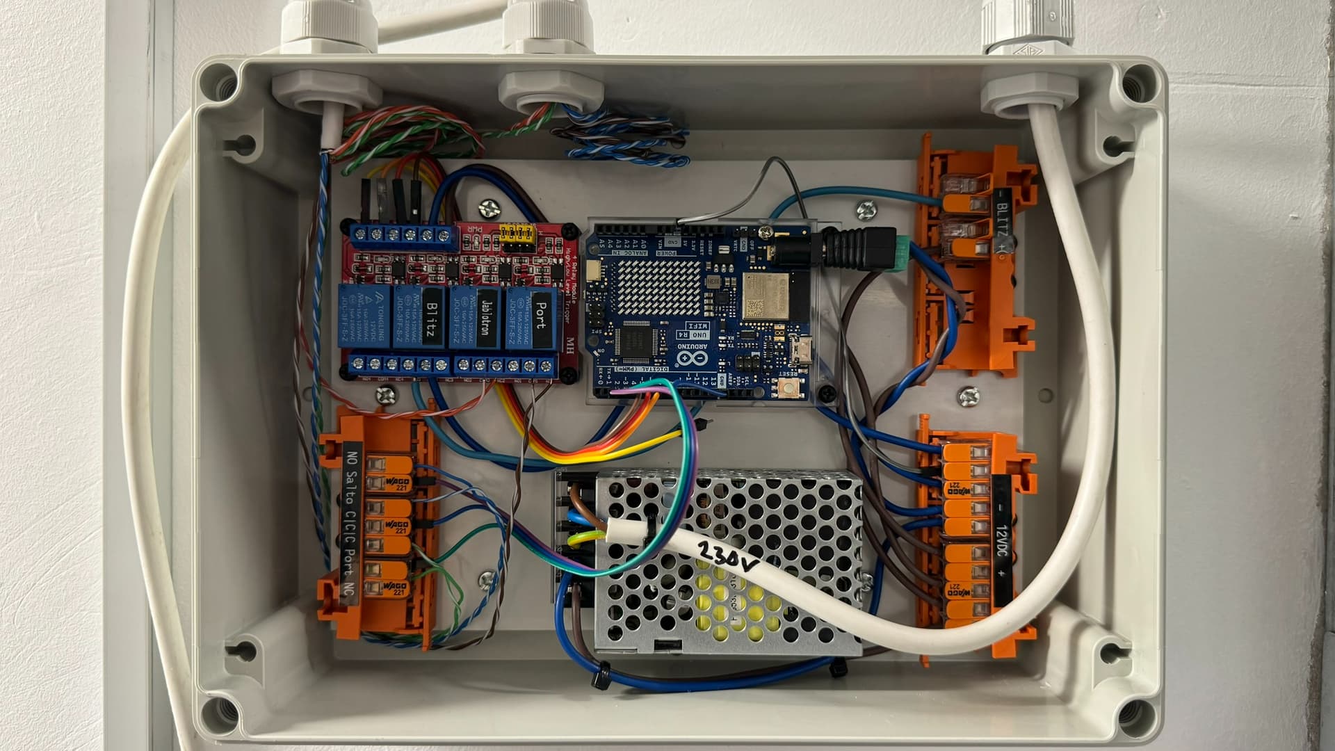
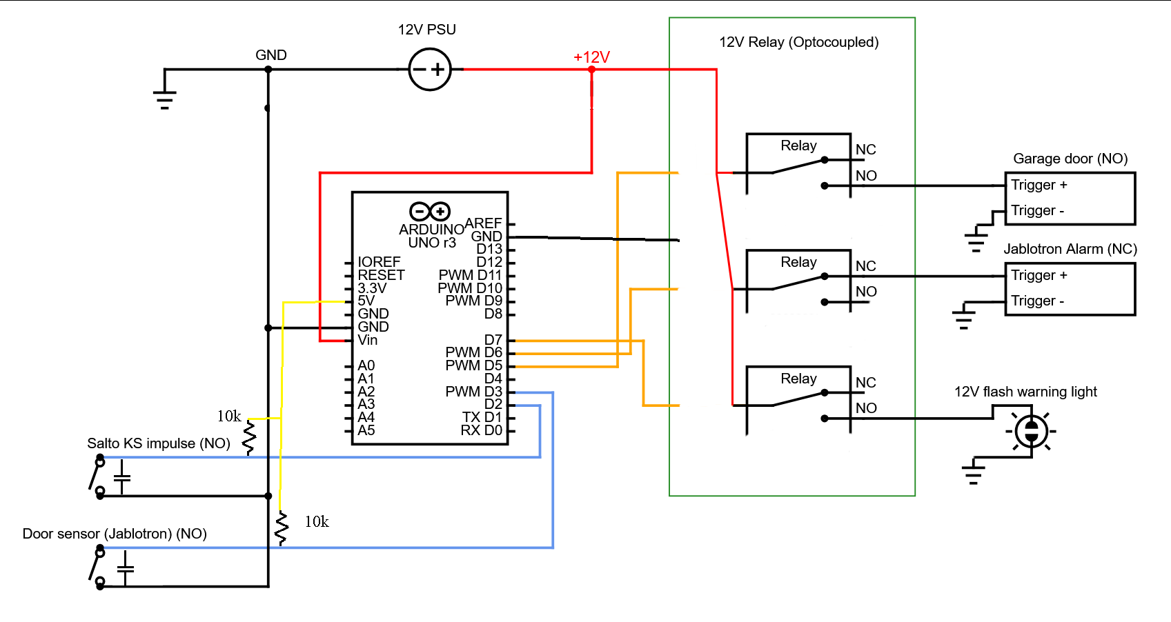
How it looks:
I've made my first attempt at a circuit diagram below - hope it makes sense. The relay is a 12V optocoupled relay, and the Arduino is running on 12V as well, but using a barrel-connector, not directly on the Vin (although I don't know if that makes any difference).