Im planning a project which will require LEDs, way more LEDs than the Arduino could ever power, so I need external power for them.
The LEDs in question are RGB Common Cathode ones, Im going to wire each color in parallel(3-4 LEDs or more, I dont know yet) while still being able to control each color individually.
Since they are Common Cathode it kinda complicates things for me, because I only have NPN transistors (yay...) to work with.
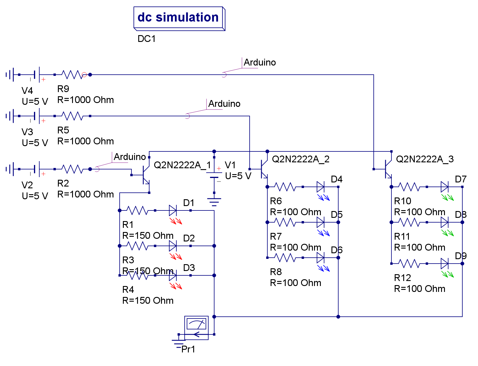
I googled around quite a lot and stumbled upon the emitter-follower method, which if I understand it correctly simply boosts the available current based on the external power, but keeps the voltage the same as Base(which will be +5V since its connected to the arduino). Now this would be perfect for me, since both the arduino and LED setup will be powered from the same 5V power brick(capable of 2.5A).
Ive been playing around in various software/simulators, and come up with a schematic that seems to work, but Id be thankful if someone with more knowledge than me could take a look at it, before I blow something up
Im not sure if the resistors from the arduino pins are needed or not though, but I added them and it seems to work fine according to various simulators.
Also, do excuse my poor drawing, Ive never done a schematic before
That will work, although you may have to adjust the LED series resistors to get the brightness you want.
One reason people usually do not use NPN transistors as "high side" switches is the drop of about 0.7 V from the transistor base to the emitter. The output voltage of a typical port pin is less than 5 V (the ATmega data sheet specifies the minimum value to be 4.2 V), so your LEDs are effectively powered by a source providing about 3.5 V.
An emitter follower has relatively high input impedance, so you don't need a resistor between the port pin and the transistor base.
Absolutely lose those base resistors, you want to minimise the voltage
across the transistor when on(*), which means bring the base right up to 5V
You still lose a forward diode drop at full current though, so check the power
dissipation is within limits. With a proper PNP high-side switch you'd get
saturation and ~ 0.1V drop.
(*) and the variation of that voltage with load current.
Thanks for the replies, I was aware of the diode voltage drop, but didnt think of the potential drop from the arduino-pin itself...
The potential drop at the Arduino pin itself will be minimal. Any drop will be mostly due to the Base-Emitter Saturation Voltage of the transistor.
This is because the datasheet claims VOH to be 4.1V when the load on the pin is 20 mA. However, the transistor will be providing most of the current (its gain will be somewhere around 100). In this configuration, the output voltage on the Arduino pin should be somewhere around 4.4V.