I have set the pins to 2,3 because I am using an UNO R4.
I am attempting to use the following encoder:
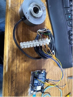
I cannot get it to read any pulses in the example code. I'm not even sure where to start to test to see what is not working. The Red wire is +5, Black Gnd Yellow pin 2 and blue pin 3
It says the encoder comes with a number of different output types. Which one disYou use?
How did You wire the encoder? Make a little drawing using pen and paper. Include the powering.
How did You declare the 2 UNO I/O pins?
Doesn't matter. Even for the simplest circuits a legible, annotated schematic can be invaluable. Consider too, that the forum is handicapped by not having as clear a picture as what you have right in front of you.
If necessary just make a hand-drawn schematic, take a photo and upload to the thread.
I installed the library you are referencing and was using that for my testing. Before I used that I got an interrupt error. To be clear I found the post you references prior and uninstalled and reinstalled per the instructions.
Now I may need to initiate the uno interrupts in the code somewhere. I don’t know much about interrupts.
As I read it there is two models. Both are identical except one has a molded cord the other a plug. Both can take 3 wiring modes I used the Line Driver Wiring Diagram. Railroader asked me to clarify the wiring in his first question and I made a simple diagram and stated the Line Driver. I could have been more clear on that I figured he understood since he was asking me what mode I wired it in.
Ok. That makes a bit more sense. And then just take there corresponding wire to ground?
The encoder wiring diagram has 3 sets of wires and the code request 2 pins. Could you explain those pins a bit. I guess I assumed that it was measuring the low and high switch between the pins.
I think you are requesting be wired in the sourcing wiring model
Thanks!!! Now it reads them in both directions instead of only 1. It still only reads using the no interrupt code. Some how I must need to initialize the interrupts since the Uno is not supported natively with the encoder code.