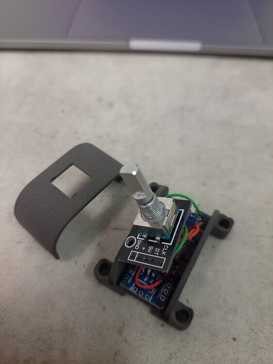
Ich mache Encoder-Impulse auswerten nie "zu Fuß" sondern nehme eine library oder einen Timer-Interrupt dafür
interrupt-basierte library demo
#include "Arduino.h"
#include "NewEncoder.h"
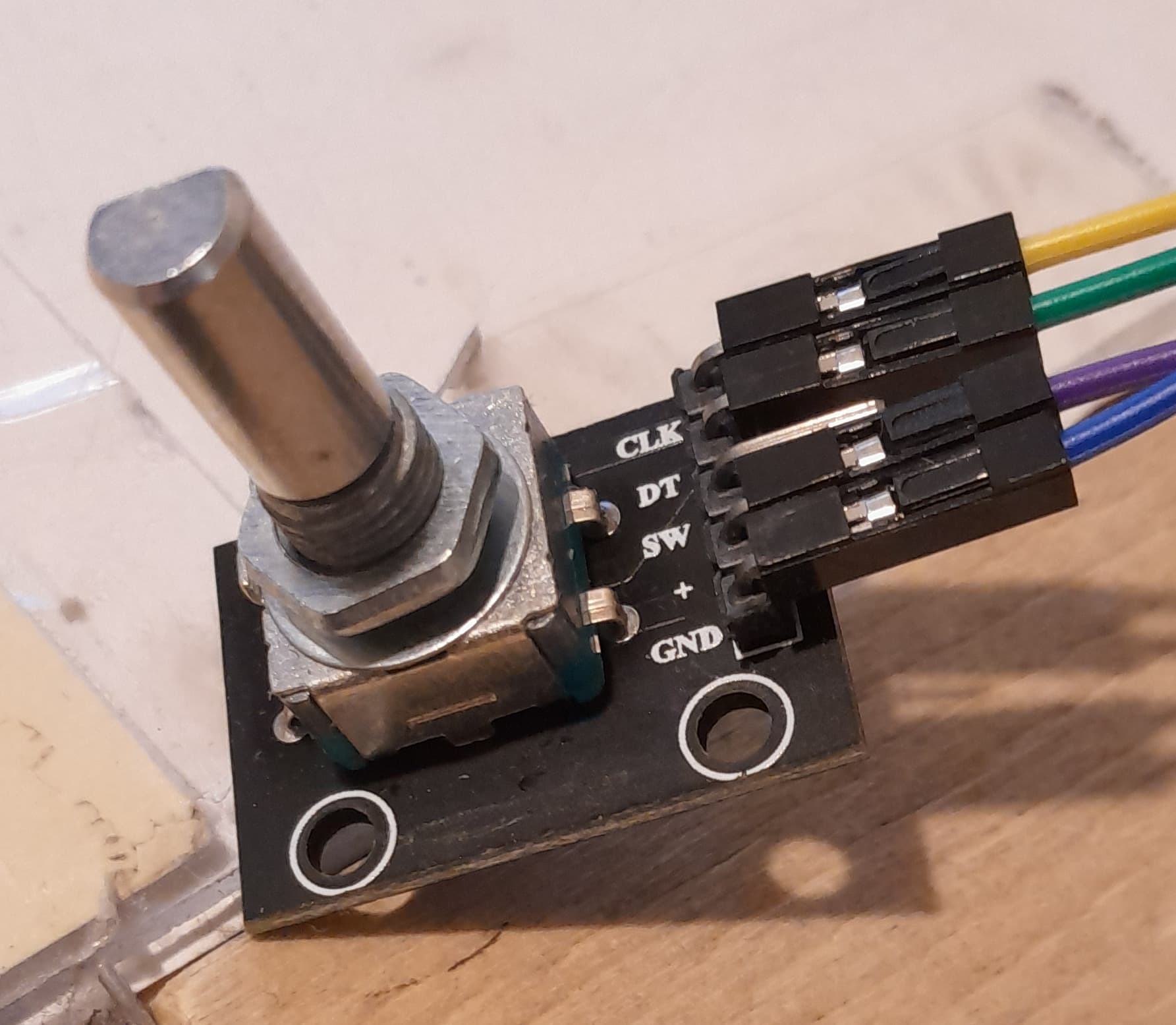
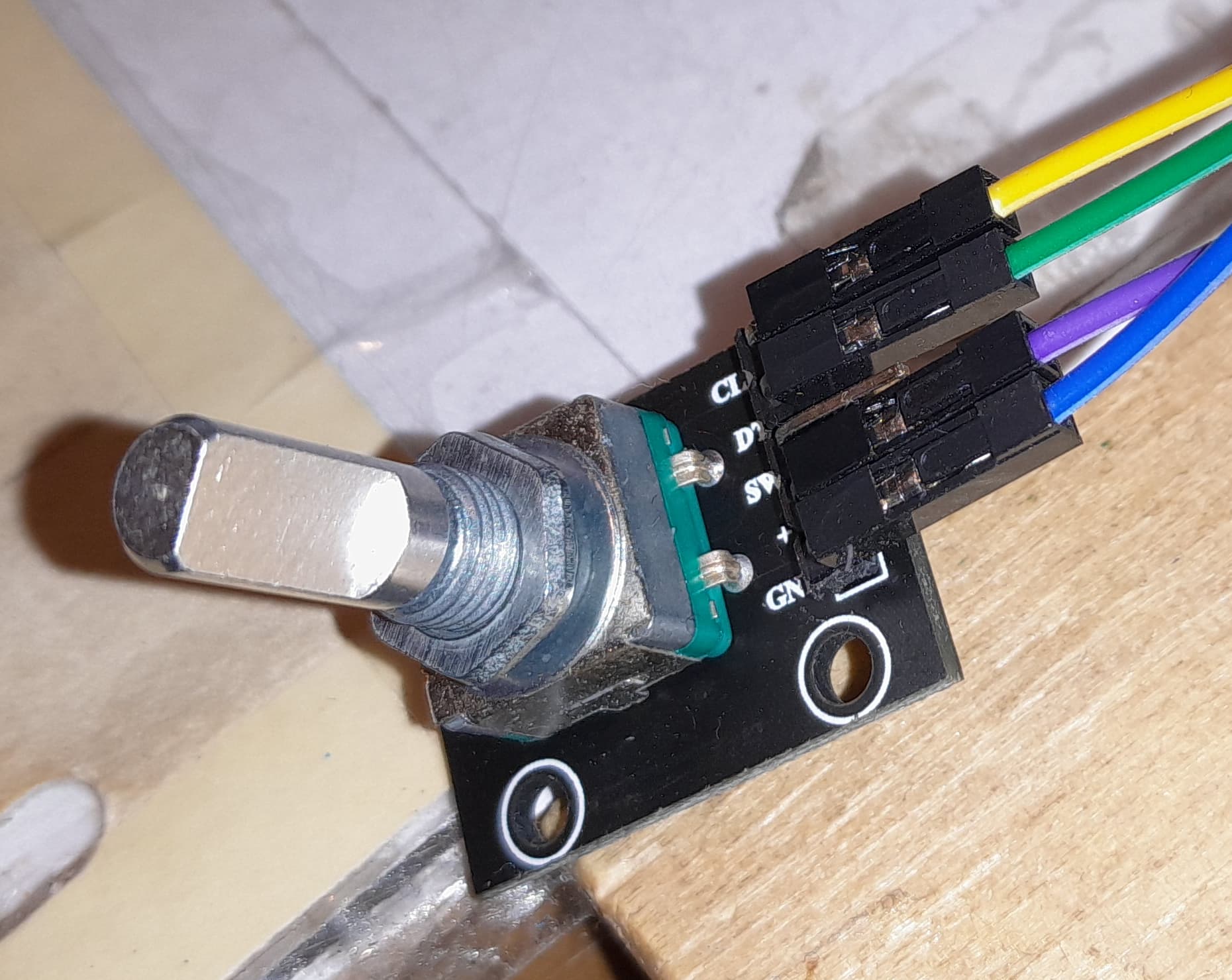
const byte EncChA_Pin = 2;
const byte EncChB_Pin = 3;
const int minVal = -20;
const int maxVal = 20;
const int startVal = 0;
// Pins 2 and 3 should work for many processors, including Uno. See README for meaning of constructor arguments.
// Use FULL_PULSE for encoders that produce one complete quadrature pulse per detnet, such as: https://www.adafruit.com/product/377
// Use HALF_PULSE for endoders that produce one complete quadrature pulse for every two detents, such as: https://www.mouser.com/ProductDetail/alps/ec11e15244g1/?qs=YMSFtX0bdJDiV4LBO61anw==&countrycode=US¤cycode=USD
NewEncoder myEncoderObject(EncChA_Pin, EncChB_Pin, minVal, maxVal, startVal, FULL_PULSE);
int16_t currentValue;
int16_t prevEncoderValue;
void setup() {
// myEncState is a variable of type EncoderState
// EncoderState is a structured variable that has two "simple" variables
// .currentValue which is type int16_t
// (16 bit signed integer valuerange -36767 to 36767)
// currentValue counts up / down with each pulse created through rotating the encoder
// and
// .currentClick which is of type "EncoderClick"
// the variable type "EncoderClick" can have just 3 values
// NoClick, DownClick, UpClick where "click" means a "pulse" created through rotating the encoder
NewEncoder::EncoderState myEncState;
Serial.begin(115200);
delay(2000);
Serial.println("Starting");
if (!myEncoderObject.begin()) {
Serial.println("Encoder Failed to Start. Check pin assignments and available interrupts. Aborting.");
while (1) {
yield();
}
} else {
// store values of currentValue and EncoderClick into variable myEncState
myEncoderObject.getState(myEncState);
Serial.print("Encoder Successfully Started at value = ");
prevEncoderValue = myEncState.currentValue;
Serial.println(prevEncoderValue);
}
}
void loop() {
NewEncoder::EncoderState myCurrentEncoderState;
// store actual values into variable myCurrentEncoderState
if (myEncoderObject.getState(myCurrentEncoderState)) {
Serial.print("Encoder: ");
currentValue = myCurrentEncoderState.currentValue;
// if currentValue has REALLY changed print new currentValue
if (currentValue != prevEncoderValue) {
Serial.println(currentValue);
prevEncoderValue = currentValue;
// if currentValue stayed the same because the number is at upper/lower limit
// check if encoder was rotated by using the UpClick / DownClick-values
} else
switch (myCurrentEncoderState.currentClick) {
case NewEncoder::UpClick:
Serial.println("at upper limit.");
break;
case NewEncoder::DownClick:
Serial.println("at lower limit.");
break;
default:
break;
}
}
}
TimerInterrupt basierte library
/* Demo-Code that uses the Rotary-library from GitHub-User https://github.com/buxtronix
 * using his library https://github.com/buxtronix/arduino/tree/master/libraries/Rotary
 * in combination with a timer-interrupt executed 10000 times per second
 * Copyright 2023 StefanL38. Licenced under the GNU GPL Version 3.
 * A T T E N T I O N !
 * this demo-code uses Timer1 which is used by other libraries too.
 * This means using this code can interfere with other libraries
 * causing malfunction of both
 *
 * This demo-code uses the TimerInterrupt.h-library from here
 * https://github.com/khoih-prog/TimerInterrupt/tree/master
 *
 * The examples in the GiPo show how to use different timers
 * The demo-code simply prints the value of variable myCounter
 * each time the value of the variable changes
 */

#define USE_TIMER_1     true

#if ( defined(__AVR_ATmega644__) || defined(__AVR_ATmega644A__) || defined(__AVR_ATmega644P__) || defined(__AVR_ATmega644PA__)  || \
        defined(ARDUINO_AVR_UNO) || defined(ARDUINO_AVR_NANO) || defined(ARDUINO_AVR_MINI) ||    defined(ARDUINO_AVR_ETHERNET) || \
        defined(ARDUINO_AVR_FIO) || defined(ARDUINO_AVR_BT)   || defined(ARDUINO_AVR_LILYPAD) || defined(ARDUINO_AVR_PRO)      || \
        defined(ARDUINO_AVR_NG) || defined(ARDUINO_AVR_UNO_WIFI_DEV_ED) || defined(ARDUINO_AVR_DUEMILANOVE) || defined(ARDUINO_AVR_FEATHER328P) || \
        defined(ARDUINO_AVR_METRO) || defined(ARDUINO_AVR_PROTRINKET5) || defined(ARDUINO_AVR_PROTRINKET3) || defined(ARDUINO_AVR_PROTRINKET5FTDI) || \
        defined(ARDUINO_AVR_PROTRINKET3FTDI) )
#endif

// To be included only in main(), .ino with setup() to avoid `Multiple Definitions` Linker Error
#include "TimerInterrupt.h"

#define TIMER1_INTERVAL_MS    1

#include <Rotary.h>

// Rotary encoder is wired with the common to ground and the two
// outputs to pins 5 and 6.
const byte channel_A_Pin = 5;
const byte channel_B_Pin = 6;
Rotary rotary = Rotary(channel_A_Pin, channel_B_Pin);

unsigned long myISR_TimerFrequency = 10000;
// myCounter that will be incremented or decremented by rotation.
// as this variable is changed in an interrupt-service-routine
// this variable MUST !! be declared volatile to make sure
// that it works properly !
volatile int8_t myCounter = 0;
int8_t last_myCounter = 0;


void TimerHandler1() {
  unsigned char result = rotary.process();

  // depending on having detected rotation
  if (result == DIR_CW) {
    myCounter++;
  }
  else if (result == DIR_CCW) {
    myCounter--;
  }
}


void PrintFileNameDateTime() {
  Serial.println( F("Code running comes from file ") );
  Serial.println( F(__FILE__) );
  Serial.print( F("  compiled ") );
  Serial.print( F(__DATE__) );
  Serial.print( F(" ") );
  Serial.println( F(__TIME__) );
}


// easy to use helper-function for non-blocking timing
boolean TimePeriodIsOver (unsigned long &startOfPeriod, unsigned long TimePeriod) {
  unsigned long currentMillis  = millis();
  if ( currentMillis - startOfPeriod >= TimePeriod ) {
    // more time than TimePeriod has elapsed since last time if-condition was true
    startOfPeriod = currentMillis; // a new period starts right here so set new starttime
    return true;
  }
  else return false;            // actual TimePeriod is NOT yet over
}

unsigned long MyTestTimer = 0;  // Timer-variables MUST be of type unsigned long
const byte    OnBoard_LED = 13;


void BlinkHeartBeatLED(int IO_Pin, int BlinkPeriod) {
  static unsigned long MyBlinkTimer;
  pinMode(IO_Pin, OUTPUT);

  if ( TimePeriodIsOver(MyBlinkTimer, BlinkPeriod) ) {
    digitalWrite(IO_Pin, !digitalRead(IO_Pin) );
  }
}


void setup() {
  Serial.begin(115200);
  Serial.println("Setup-Start");
  PrintFileNameDateTime();

  Serial.print(F("\nStarting Argument_None on "));
  Serial.println(BOARD_TYPE);
  Serial.println(TIMER_INTERRUPT_VERSION);
  Serial.print(F("CPU Frequency = "));
  Serial.print(F_CPU / 1000000);
  Serial.println(F(" MHz"));

  // Timer0 is used for micros(), millis(), delay(), etc and can't be used
  // Select Timer 1-2 for UNO, 1-5 for MEGA, 1,3,4 for 16u4/32u4
  // Timer 2 is 8-bit timer, only for higher frequency
  // Timer 4 of 16u4 and 32u4 is 8/10-bit timer, only for higher frequency

  ITimer1.init();

  // Using ATmega328 used in UNO => 16MHz CPU clock ,
  // For 16-bit timer 1, 3, 4 and 5, set frequency from 0.2385 to some KHz
  // For 8-bit timer 2 (prescaler up to 1024, set frequency from 61.5Hz to some KHz

  if (ITimer1.attachInterruptInterval(TIMER1_INTERVAL_MS, TimerHandler1)) {
    Serial.print(F("Starting  ITimer1 OK, millis() = ")); Serial.println(millis());
  }
  else {
    Serial.println(F("Can't set ITimer1. Select another freq. or timer"));
  }
}


void loop() {

  BlinkHeartBeatLED(OnBoard_LED, 250);

  // check if value has changed
  if (last_myCounter != myCounter) {
    // only if value REALLY HAS changed
    byte difference = abs(last_myCounter - myCounter);
    if (difference != 1) {
      Serial.println("difference != 1 counter jumped !!");
    }
    last_myCounter = myCounter; // update last_myCounter
    Serial.print("myCounter=");
    Serial.println(myCounter);
  }
}
vgs