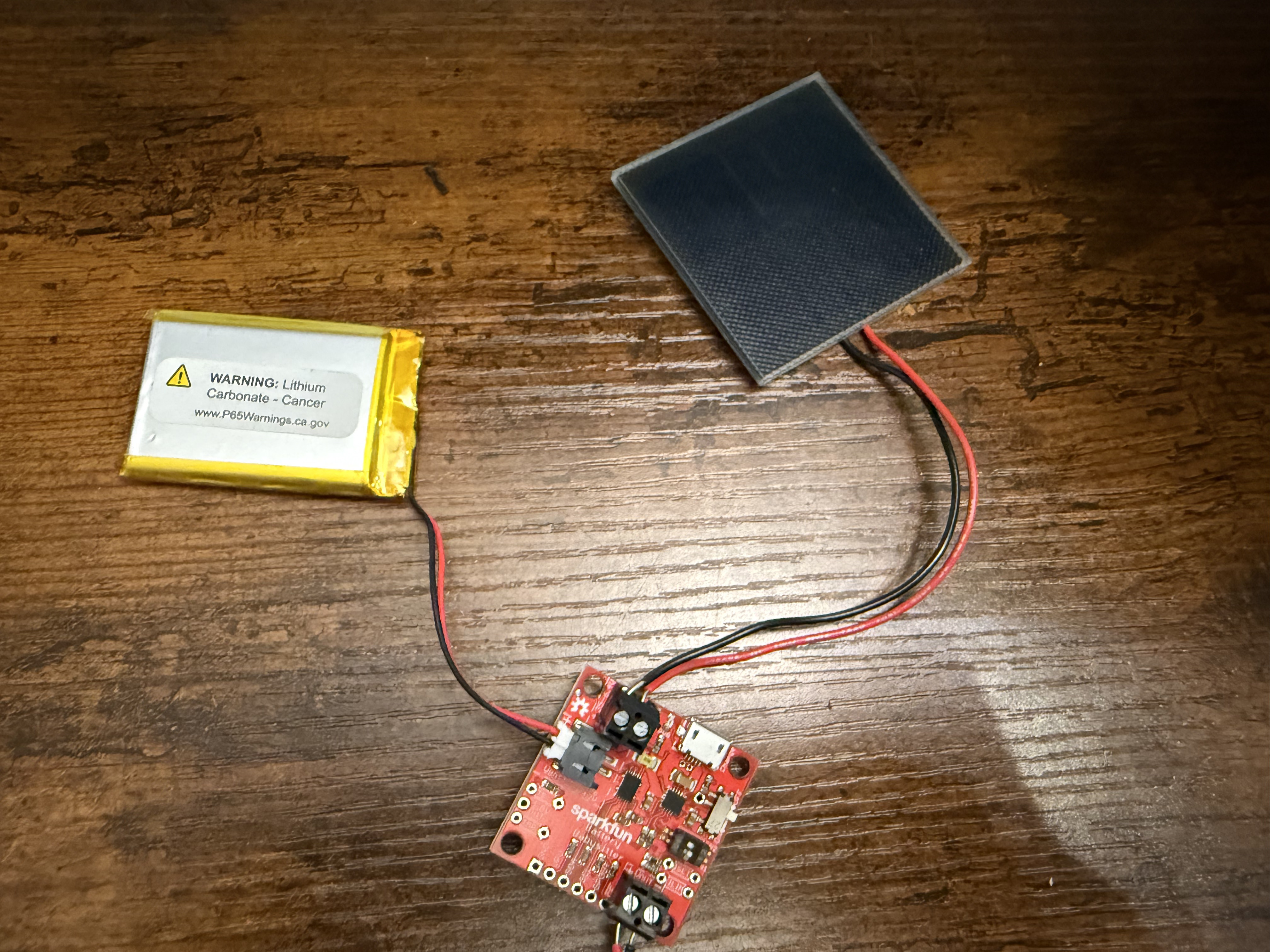
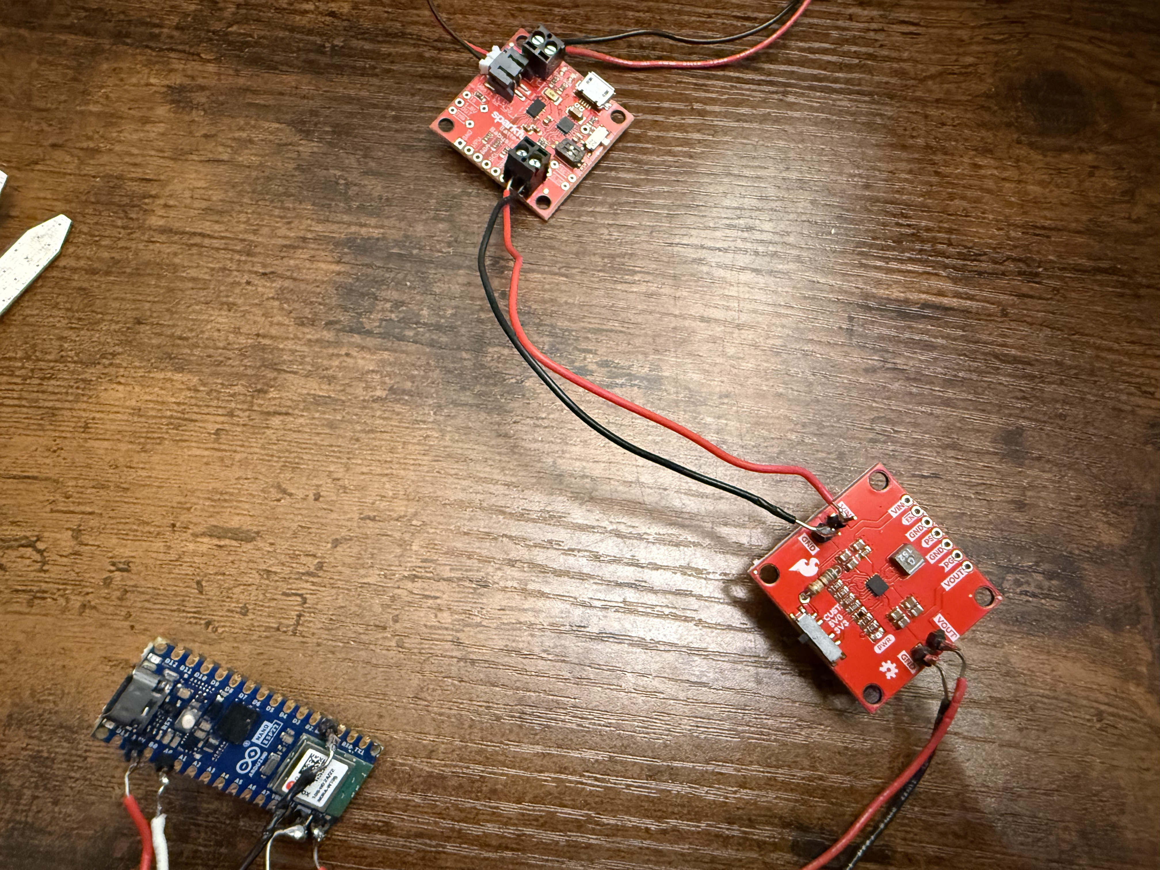
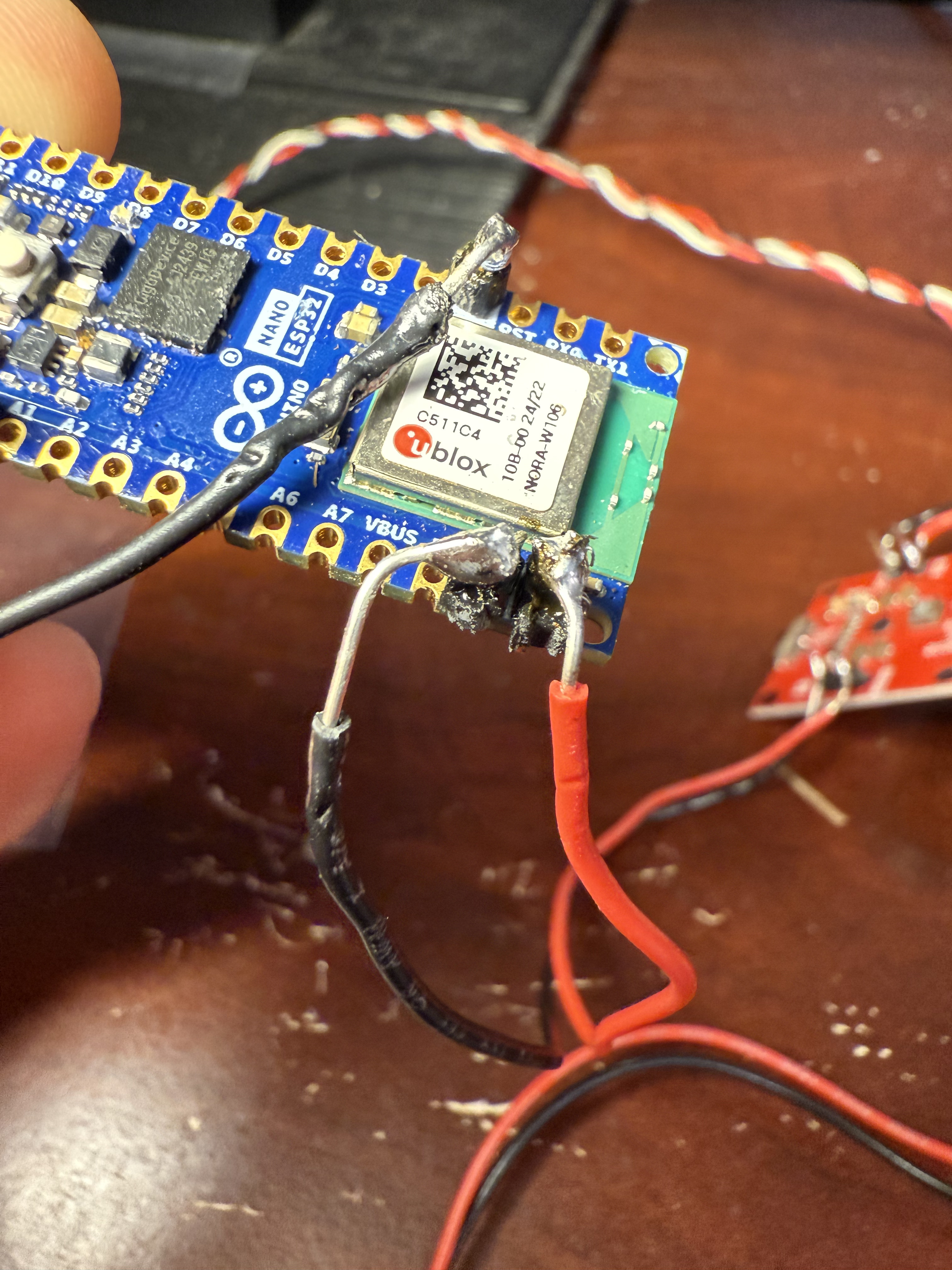
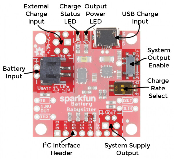
I have a 6V 0.3 Watt solar panel connected to the Babysitter, which connects to a buck boost converter that is connected to the Vin/ground pins on an Arduino Nano ESP32. The reason for the buck boost converter is that is the output voltage of the babysitter is not high enough to power the ESP32.
The solar panel works and the battery charges, but I'm not getting any power to the Arduino and I'm not sure why.
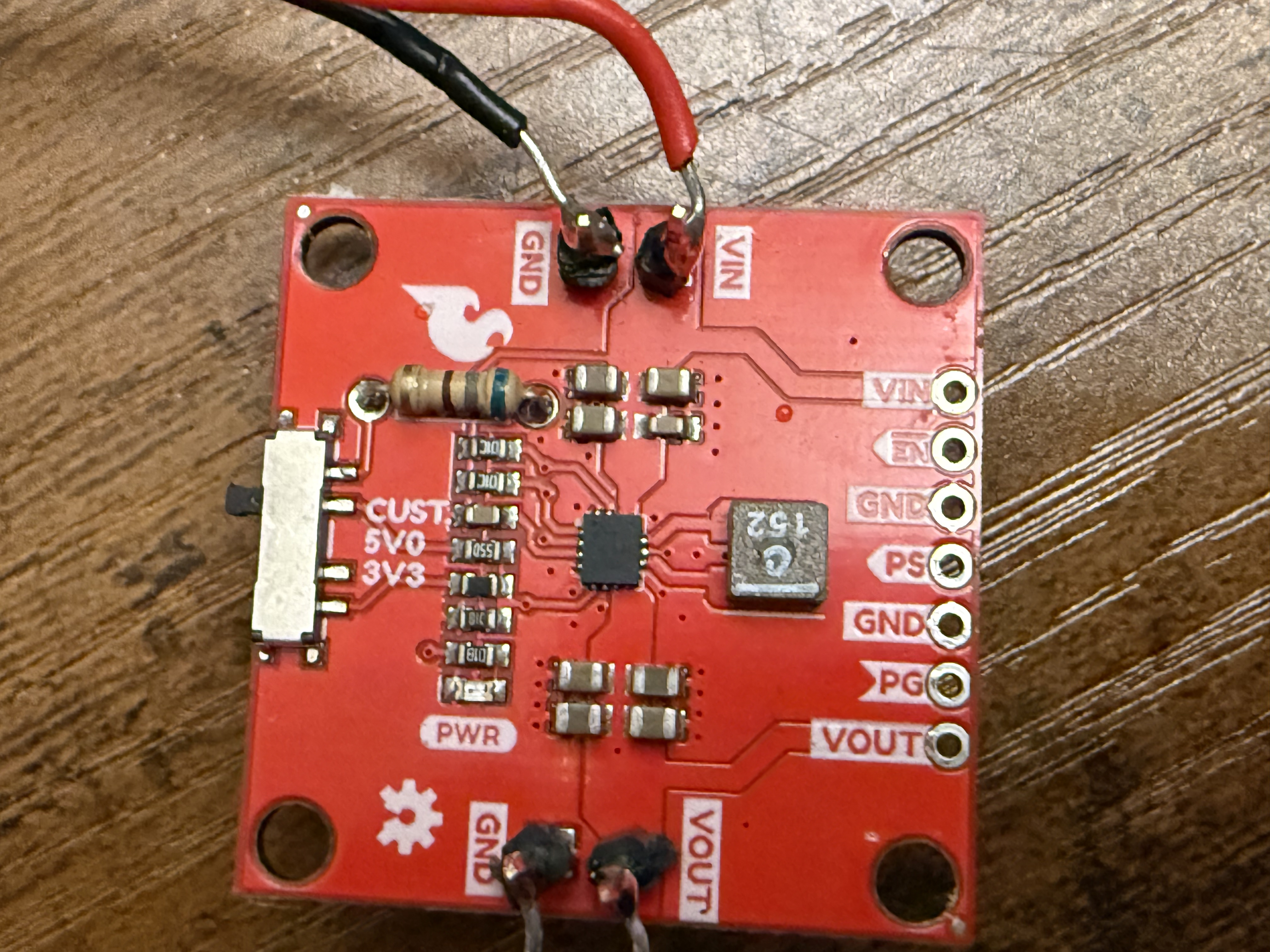
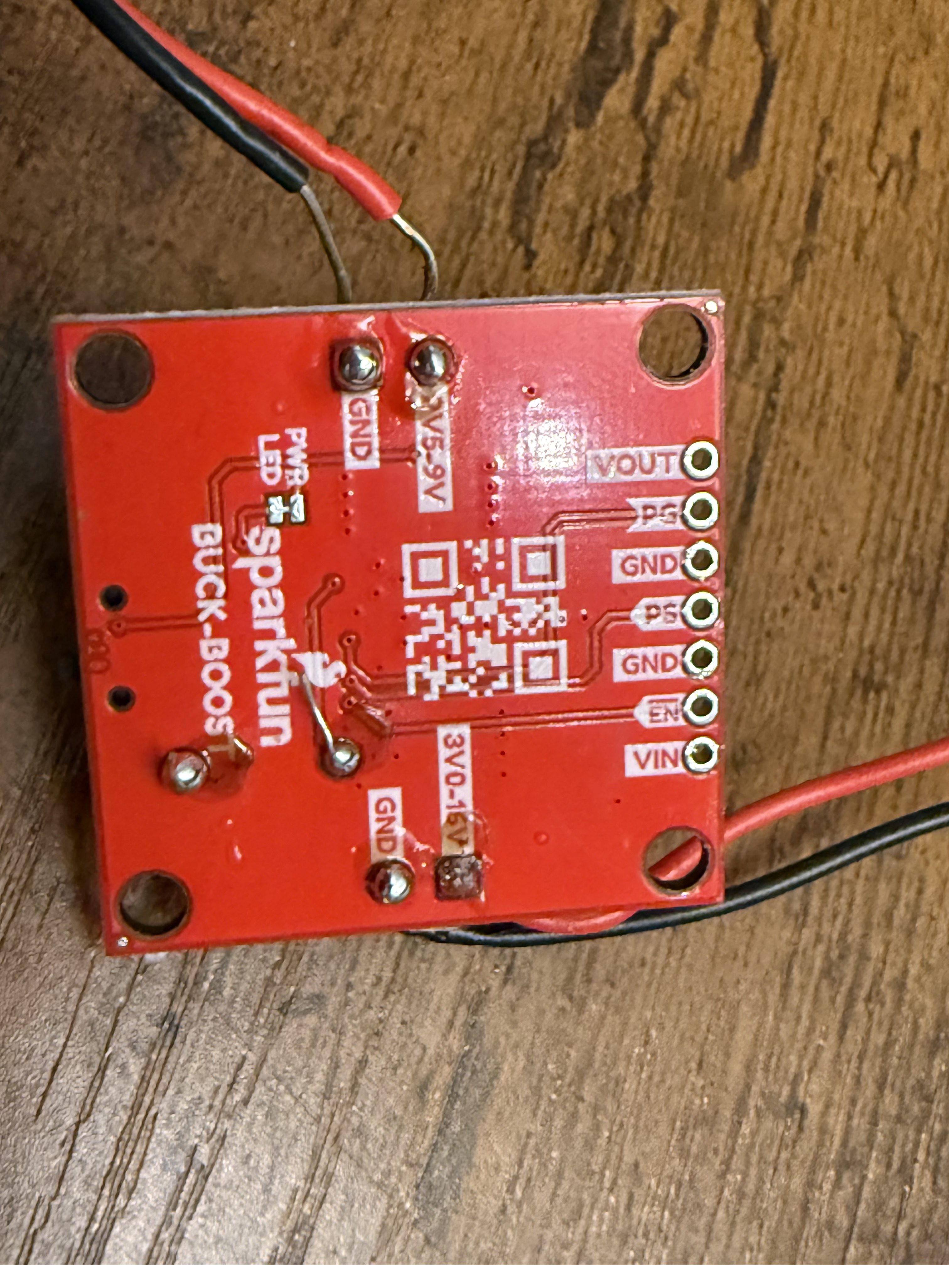
I have to agree with @jim-p and say it is highly probable you have a bad solder connection. It is very hard to tell as the joints have not been cleaned. Isopropyl alcohol 91% and some cotton tipped swabs works great for me.
I recommend getting some materials to practice your soldering skills. From what I can see, you may not be heating the solder enough for it to flow properly, and you might not be using enough of the proper flux. Practicing on old boards will allow you to experiment without risking damage to valuable components.
Soldering Tips:
Use the Right Solder: I prefer 60/40 solder with a Rosin core flux because it’s easier to work with. For more information on different types of solder, you can check out this guide: Types of Solder.
Temperature Control Matters: Soldering is a basic skill in electronics, and mastering it is crucial if you plan to continue in this field. While inexpensive irons can melt solder, they often lack the precision needed for good results. Investing in a soldering workstation with temperature control is ideal.
Practice Makes Perfect: Practice on old circuit boards to build your skills without risking damage to your current projects.
Lead-Free Solder Considerations: Note that lead-free solders require higher temperatures, and some older soldering irons may not reach the necessary heat. Ensure your equipment is up to the task.
Are you sure that charger board can work with a solar panel. Solar panels are mainly current sources, not voltage sources like a supply or battery.
The panel also seems way too small to be effective.
That doesn't explain why the boost converter doesn't work from a fully charged battery.
Leo..
Well that is a problem and needs to be solved first.
Disconnect the buck/boost and the solar panel then measure the voltage output from the babysitter.
Hi, @mfusco
As @Etienne_74 has pointed out;
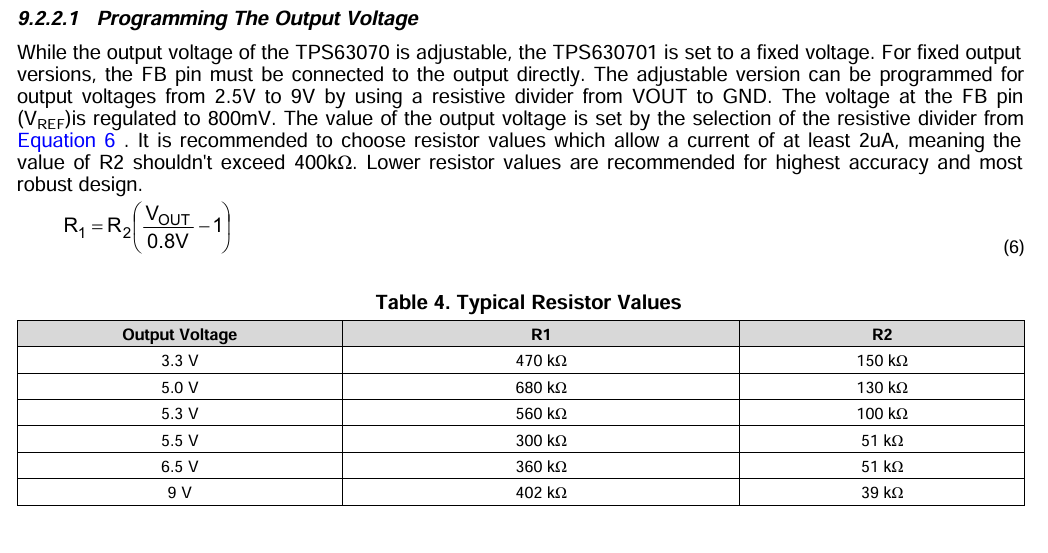
Badly written equation, BODMAS.
R = 68.1 x ((8.7 / 0.8)-1) KOhms
R = 68.1 x ( 10.8 - 1) KOms
R = 68.1 x 9.8 KOhms
R = 672.4 KOhms
R = 680 KOhms.
This bit is essential; Can you please post a copy of your circuit, a picture of a hand drawn circuit in jpg, png? Hand drawn and photographed is perfectly acceptable. Please include ALL hardware, power supplies, component names and pin labels.