ESP-01S on Arduino MEGA 2560 - A fatal esptool.py error occurred: Failed to connect to ESP8266: Timed out waiting for packet header

Hi!
I've been trying to make an ESP-01S work with an Arduino MEGA 2560 for 3 days now, reading countless threads and guides without success.

The equipment:

Controllers:
ESP-01S:
https://www.amazon.ca/dp/B00O34AGSU?psc=1&ref=ppx_yo2ov_dt_b_product_details
Arduino MEGA 2560 R3:
https://www.amazon.ca/dp/B01H4ZLZLQ?psc=1&ref=ppx_yo2ov_dt_b_product_details
LF33CV:
https://www.mouser.ca/ProductDetail/STMicroelectronics/LF33CV?qs=LPKLnBpMevjK%252B28MZYQO9Q%3D%3D
Power supply 5V60A:
https://www.amazon.ca/gp/product/B01D8FLZV6/ref=ppx_yo_dt_b_search_asin_title?ie=UTF8&th=1

The software:
Arduino IDE 2.3.2
Board manager esp8266 by ESP8266 community 3.1.2

IDE preferences setup showing the additional board manager which I use:

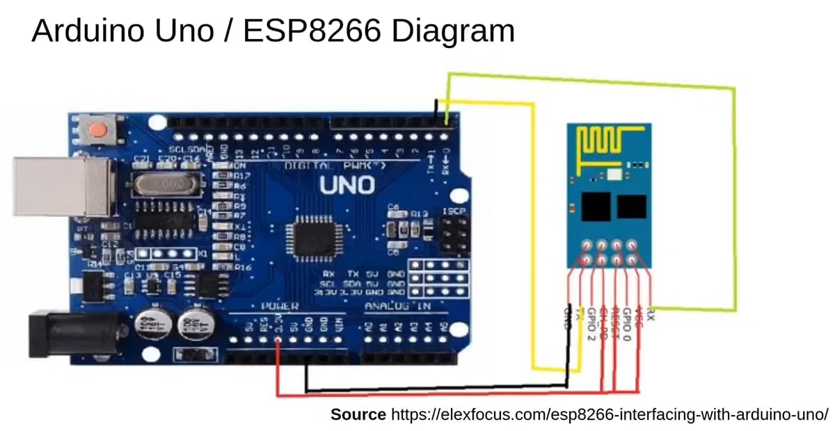
Here is the wiring schematic I followed, it show a UNO but thats how I wired the MEGA on the ESP-01S:

Power:
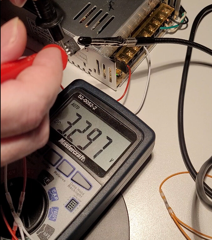
I found a couple of threads mentioning the Arduino's 3v3 volt pin not having enough mA to actually drive the ESP-01S so I used an LF33CV regulator to modulate the 5V I'm getting from the 5V60A power supply to 3.3V:

Here is the result:

The schematic I'm using with the power supply and LF33CV looks like that:

Wiring:
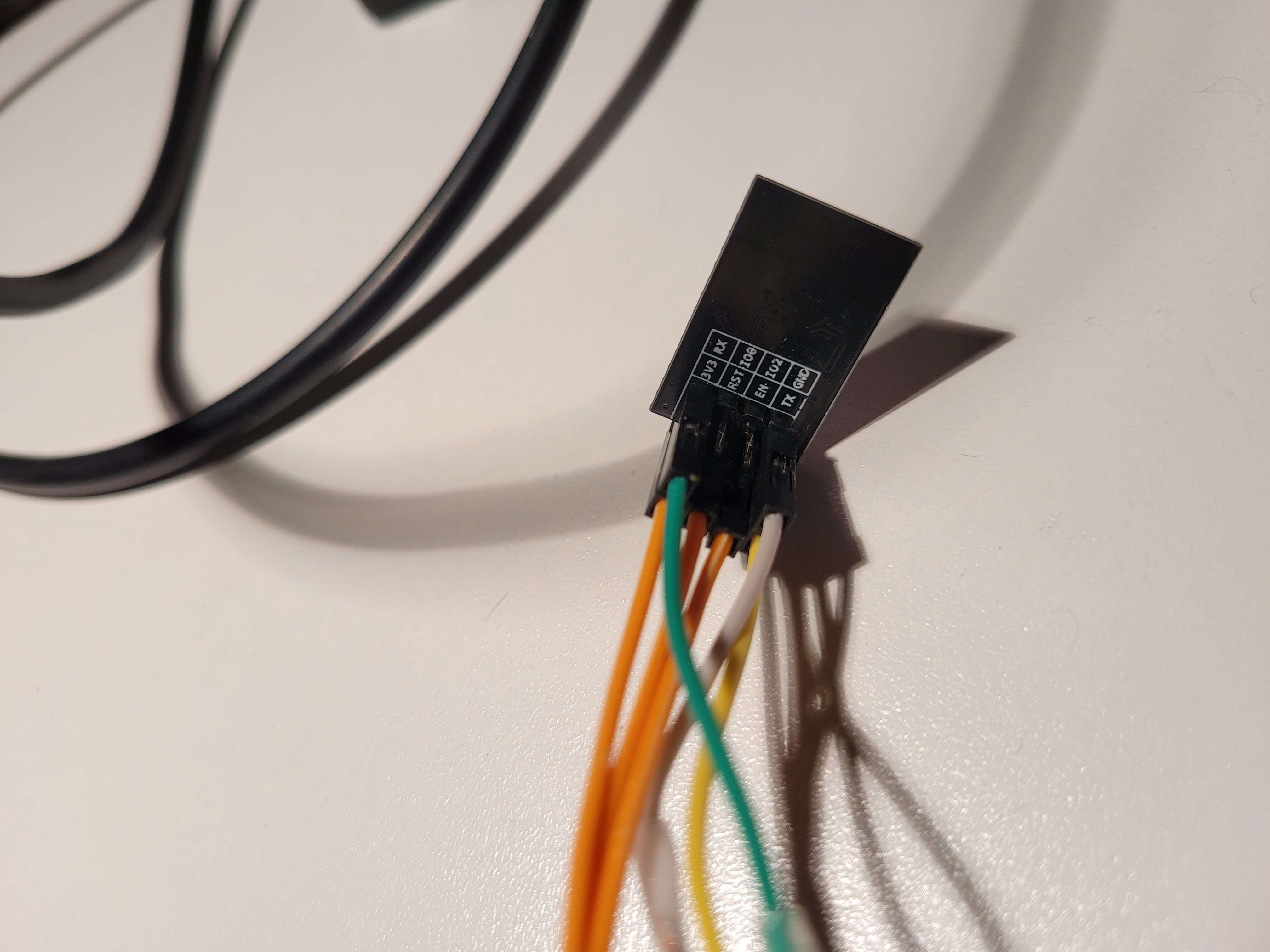
Here is what the ESP-01S wiring looks like:

The live wire coming from the LF33CV is split into these 3 orange wires:


Here is the back of the chip where you can see them plugged in the [3v3/VCC], [RST] and [EN/CH_PD] pins:

The ground wiring is the white wire that goes between the LF33CV's center pin, Arduino's GND pin and the ESP-01S GND pin:

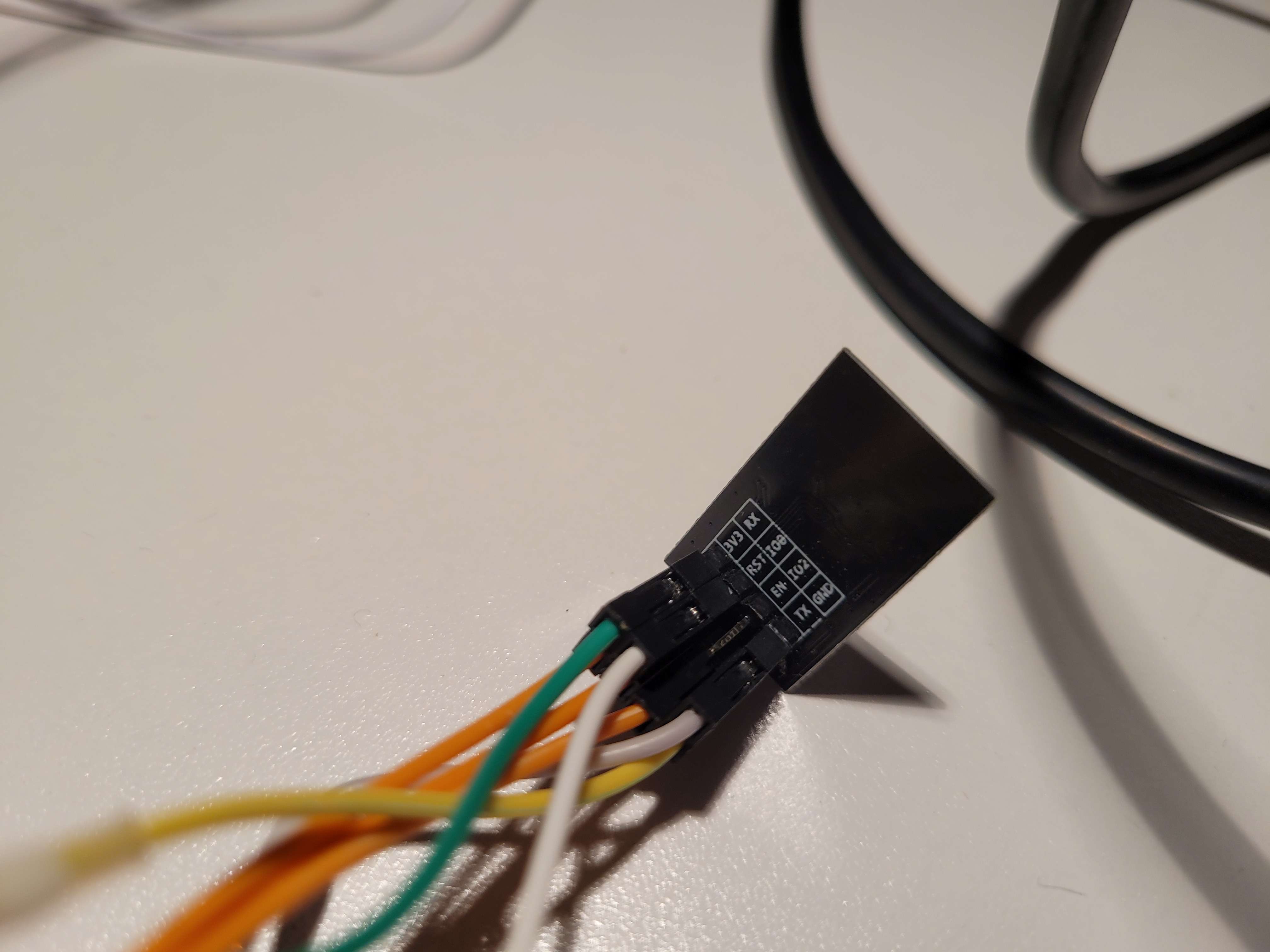
The MEGA GND pin (white), RX pin (green) and TX pin (yellow) wired:

The ESP-01S with the GND, RX and TX pins:

The overall setup view:

Here is a video of the chip booting where we can see the blue led blink:

In the Arduino IDE I have the the right COM port and able to upload sketches to the MEGA 2560:

For the time being I uploaded an empty script to make sure nothing interfere with the ESP-01S.

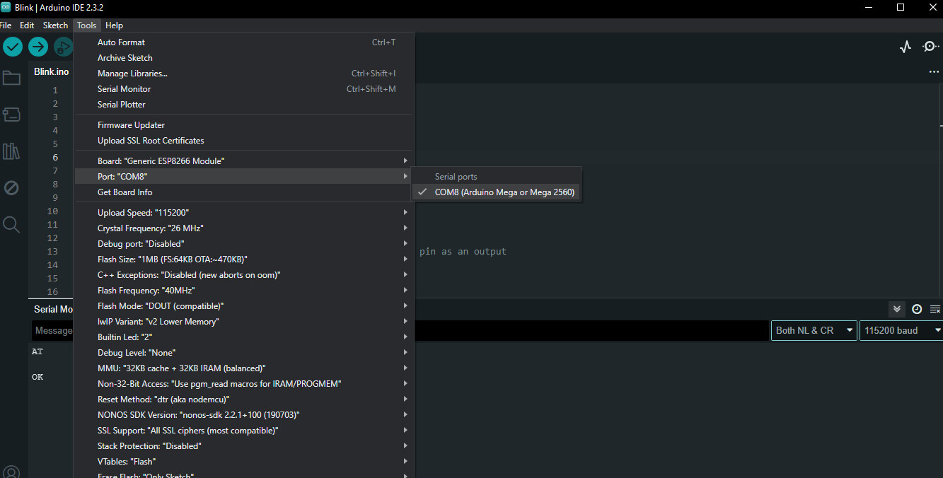
I then selected the "Generic ESP8266 Module" board to switch the IDE to communicate with the ESP-01S instead of the MEGA:


After doing this the selected board showing in the top left box of the IDE display "Generic ESP8266 Module"

In this wiring configuration if I setup the serial monitor to use "Both NL & CR" along with the 115200 baud I'm able to send AT commands that I believe are getting reponses from the ESP-01S.
The following AT: Responses show up:

AT:
OK

AT+RST:
OK

AT+GMR:
AT version:1.7.5.0(Oct 9 2021 09:26:04)
SDK version:3.0.5(b29dcd3)
compile time:Sep 15 2022 20:04:36
OK

AT+CWMODE?:
+CWMODE:2
OK

So it seems like the ESP-01S is responding to AT commands but as when I try to upload the Blink script that come with the ESP8266 Examples scripts of the Arduino IDE to the ESP-01S I'm always getting the following time out error:

. Variables and constants in RAM (global, static), used 28080 / 80192 bytes (35%)
║   SEGMENT  BYTES    DESCRIPTION
╠══ DATA     1496     initialized variables
╠══ RODATA   920      constants       
╚══ BSS      25664    zeroed variables
. Instruction RAM (IRAM_ATTR, ICACHE_RAM_ATTR), used 59667 / 65536 bytes (91%)
║   SEGMENT  BYTES    DESCRIPTION
╠══ ICACHE   32768    reserved space for flash instruction cache
╚══ IRAM     26899    code in IRAM    
. Code in flash (default, ICACHE_FLASH_ATTR), used 231732 / 1048576 bytes (22%)
║   SEGMENT  BYTES    DESCRIPTION
╚══ IROM     231732   code in flash   
esptool.py v3.0
Serial port COM9
Connecting........_____....._____....._____....._____....._____....._____....._____
A fatal esptool.py error occurred: Failed to connect to ESP8266: Timed out waiting for packet header

Then I tried pulling the ESP-01S GPIO0 LOW since I read this is required to set the ESP-01S into "flashing" mode which would be required for uploading sketches to it?
Since nothing worked yet I'm not even sure this is the right thing to do, it sounded like a config if you want to flash the firmware, not uploading a simple script to it... but I tried it.
The ground wiring I connected to the IO0 pin:

Here is the overall setup again but this time WITH the ESP-01S's GPIO0 pulled LOW which has the ground wire connected / split between the LF33CV, MEGA and ESP-01S GND and GPIO0 pins:

The schematic looks like that at this stage:

And this time around when I upload a sketch to the ESP-01S I do see a lot of activity from its blue led that sometimes even blink at the same rhythm as the MEGA led:

Obviously I was having a moment of high hope that was utterly crushed by the same very annoying time out error :unamused:

I tried uploading from 2 different computers, used 3 different serial wires and didn't use extensions or anything like that.
Always getting this time out error.

I'm a bit confused by some threads stating that TX should be wired to RX?
I'm not getting anywhere when I use this configuration (uploading sketch and AT commands, nothing work) but I'm probably missing fundamental details about that too.

Does anybody here has an idea of what I'm missing?

Any help will be greatly appreciated.

Press and hold the reset button on the Mega, and then try to upload the code.

off topic ... try to make some basic examples like blink or interrupts in costycnc.it/avr1 from where directly from webpage you can compile asm and send to arduino quickly ... in this mode you can learn some base about internal arduino registers, interrupts , ecc and will help you learn better the arduino and microcontrollers in general... i ricord you that you can not make big programs in assembler ... only help you understand how low lewel program works and internal arduino in specially atmega328! good job!

That is fine i use that same method.

So that is good news, step 1 is completed. I now do want to urge you to put a voltage divider on the ESP's RX pin to reduce the 5v logic levels coming in to it to 3.3v The RX pin is not 5v tolerant on an ESP-01 and it will break at some point if you feed 5v into it.

MEGA -> 1K -> ESP-RX -> 1K -> 1K -> GND

Yes to upload sketches or uploading firmware, it is required to pull GPIO0 LOW.

Well to upload sketches or flash the firmware is the same thing. Once you upload a sketch you overwrite the existing AT-command software.

It is confusing, the idea behind this that if you still have the AT-command firmware, you could use the Mega to communicate with the esp by sending at-commands to it. This can also be done once you upload your own firmware (a sketch) but then you need to make sure the esp has a sketch / firmware on it that handles the Serial communication.

So you are getting somewhere, first add the voltage divider and use 1K resistors as recommended (not 10K or something like that)

Check and see if the at-commands are still working. If so that means you have not uploaded anything.
My statement again tells you that once you upload a sketch, you overwrite the AT command firmware by doing so. (it can be re-uploaded if you really want to)

Pulling GPIO 0 LOW, means that it should be pulled LOW at boot.
What i do is that i connect a 10K resistor between Vcc (3.3v) and RST and then connect a push button between RST & GND, so i can easily reset the ESP-01
Now pull GPIO 0 LOW and reset the ESP.

So which sketch did you try to upload ?

I always tend to start out with blink, and use the intenal led that on nearly all ESP-01's is on GPIO1

First of all I want to thank you all for taking time to read my wall of text and providing suggestions and ideas to try out.

Always amazed by the community and how lucky we are to have people getting out of their way to help others with their project.

Been working on mine for about 2 years and adding WIFI support to transmit simple operations from PC -> WIFI -> ESP-01S -> MEGA is the final step.

@jobitjoseph went straight for the eyes and pointed the very important missing step where you need to hold the MEGA reset button while uploading a script to the ESP-01S, this video start when I just pressed the upload button in the Arduino IDE:

Pure joy when I saw this :astonished: :

Then you just need to unplug the ground from the GPIO0 pin to put the ESP-01S back in "normal" operation mode:

An finally looking at blink running on the ESP-01S:

@Deva_Rishi
The ESP-01S is powered by the 5V60A power supply which is very stable and power the ESP-01S through the LF33CV which provide an also stable 3.3V so I don't see why a voltage divider on the ESP's RX pin would be necessary?

Thkx for confirming the semantic around flashing vs uploading and they are indeed the same thing.
Most of the time the term used when sending a sketch to an Arduino is "uploading" and suddenly for the ESP-01S I was sometimes reading flashing or uploading depending on the documentation or thread and I was wondering if there was a different process to flash the firmware (hence the hold the reset button etc...) on an onboard chip of the ESP while uploading sketch was akin to uploading to an Arduino with a more straightforward way BUT, turn out its all the same and the pull GPIO0 LOW + hold the reset button while uploading to ESP-01S is the standard way to upload/flash a sketch to this board "through" the Arduino controller.

All these little notes about having the pulled low at boot were also welcome but I'm sure glad I didn't had to get an extra push button (I don't have one atm) and the reset button of the MEGA was enough.

I'm very happy to say that its working now and glad the code side for the MEGA and ESP-01S (to communicate between each other) can finally start tonight!

Thank you very much for the help, its super appreciated! :smiley:

You all rock!

Because the ESP-01 is a 3.3v device and expects 3.3v logic levels, while the Mega is a 5v device and uses 5v logic levels. If the ESP is the output and the Mega is the input, this is not a problem, 3.3v logic HIGH is enough to switch a 5v logic INPUT to high. The other direction though you are exposing the ESP RX pin to 5v logic levels while it is rated only for 3.3v . Hence the voltage divider to drop the Mega's 5v logic HIGH to a more decent 3.33v as a logic HIGH for a 3.3v device.

I see, this is a very eye opening tip right there, I'll follow your suggestion, thkx a lot @Deva_Rishi! :grinning:

@Deva_Rishi so if I follow your steps correctly, in order to protect the 3.3V RX input pin of the ESP-01S when connected in serial communication mode (TX -> RX and RX -> TX) from the 5V TX output pin:

MEGA -> 1K -> ESP-RX -> 1K -> 1K -> GND

The schematic would look like this?

Where I put a 1K resistor between the MEGA TX and ESP RX pin.
And 2 back to back 1K resistor between the MEGA GND and the ESP GND.

Just making a sanity check if I got this right.

No that's wrong. You need to move the 2 1K resistors so they sit between ESP RX & (common) GND. like that if the Mega TX is HIGH and at 5v, the ESP RX will be at 3.3v

1 Like

Thank you very much @Deva_Rishi for the correction, I'm learning a lot atm and appreciate your awesome insight and patience, hopefully this thread will help others in the future. :slight_smile:

Last night I got my first webserver loaded on the ESP-01S and can interface with it through WIFI and today I'm working on the serial communication between the ESP-01S and MEGA so I'll proceed to wire the resistor like you taught me and see where it goes!

This topic was automatically closed 180 days after the last reply. New replies are no longer allowed.