Hello fellow people!
I am having some trouble adding internet access to my Arduino Nano using the ESP-01. I have tried numerous methods for wiring the circuit and interfacing with it through the Arduino.
Board References
Here is a link to the Arduino Nano for reference: https://128217-368301-raikfcquaxqncofqfm.stackpathdns.com/wp-content/uploads/2017/06/NSE-1004-2_7.jpg
It may be worth noting that I am using a clone of the board. Here is the exact board: Amazon.com
For the ESP-01, here is a reference: https://components101.com/sites/default/files/component_pin/ESP8266-Pinout.png
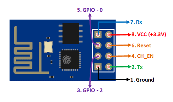
My Code
I am using the WiFiESP library available here: GitHub - bportaluri/WiFiEsp: Arduino WiFi library for ESP8266 modules
And I am using the code given as an example by that library, specifically this one: WiFiEsp/WebClientRepeating.ino at master · bportaluri/WiFiEsp · GitHub
The Results
When I upload the program, I receive the message:
[WiFiEsp] Initializing ESP module
[WiFiEsp] >>> TIMEOUT >>>
[WiFiEsp] >>> TIMEOUT >>>
[WiFiEsp] >>> TIMEOUT >>>
[WiFiEsp] >>> TIMEOUT >>>
[WiFiEsp] >>> TIMEOUT >>>
[WiFiEsp] Cannot initialize ESP module
[WiFiEsp] >>> TIMEOUT >>>
[WiFiEsp] No tag found
WiFi shield not present
I tried using an AT command but received no response. I am not sure that I am doing this correctly. I have tried every baud rate available, typed AT into the Serial Monitor, and clicked send. In the updates below, I was able to run a few commands in this way. This stopped working after a while though. I have no idea why.
In fact, there is only one thing I can get to display from the board. When the serial monitor is set to 74880 baud, and I connect CH_EN to 3.3v, I get the message:
 ets Jan  8 2013,rst cause:1, boot mode:(3,6)

load 0x40100000, len 2408, room 16
tail 8
chksum 0xe5
load 0x3ffe8000, len 776, room 0
tail 8
chksum 0x84
load 0x3ffe8310, len 632, room 0
tail 8
chksum 0xd8
csum 0xd8

2nd boot version : 1.6
  SPI Speed      : 40MHz
  SPI Mode       : QIO
  SPI Flash Size & Map: 8Mbit(512KB+512KB)
jump to run user1 @ 1000
A Note on Lights
The LED's on the ESP-01 behave in the following ways:
- When CH_EN is first connected and the above output shows, the red light turns on and the blue light flashes briefly. This does not always occur, in which case just the red light turns on.
-When CH_EN and VCC are connected, the red light stays on.
Attempted changes to the code
-
Seeing as this message is only readable when the board is at 74880 Baud, I tried changing the Serial command in the code to use this rate. I have tried this on both as well as each individually.
-
I have tried uploading a blank sketch to to AT commands. No response.
Attempted Circuits
-VCC and CH_EN connected to 3.3v, GND to GND, RX to RXO, TX to TXI.
-VCC and CH_EN connected to 3.3v, GND to GND, RX to 6, TX to 7.
-VCC and CH_EN connected to 3.3v, GND to GND, RX to 7, TX to 6.
-VCC and CH_EN connected to 3.3v of an external power supply, GND to GND of an external power supply, previous three versions of RX and TX.
-Various combinations of the above utilizing 1, 2, and 10k ohms.
The only thing I haven't been able to try is connecting to 5v with a voltage manager as I do not have one.
Conclusion
I have no idea what else to try at this point and I would really appreciate some help. I have looked on every forum, YouTube video, and website with no luck. I would be grateful if someone could help me solve this!
UPDATES
2020-03-27
- I was able to get a response from the board by following the tutorial linked below. I needed to connect GPIO 0 to VCC, and change the Serial Monitor from "New Line" to "New Line Carriage Return" (Literally "Both NL & CR"). https://www.hackster.io/ROBINTHOMAS/programming-esp8266-esp-01-with-arduino-011389
-I am still getting the TIMEOUT error when I upload the sketch provided by WiFiEsp
-
I have successfully connected the ESP-01 to WiFi via AT commands. This does not fix the problem with WiFiEsp.
-
Notably, the AT commands only seem to work when I have uploaded a blank sketch. When my program is running, it does not work.
-
Back to square one. I am no longer receiving responses to my AT commands. I have no idea what is wrong. Now, when the reset pin is high, none of the LED's are on.
2020-03-28
-
I have regained access to the AT commands. It only works when ESP01 VCC is connected to 5v, and CH_EN is connected to 3.3v. I am aware that the module is supposed to be connected to 3.3v, but that did not work. This only works with a blank sketch. Even if I only include Serial.begin(115200), I can no longer run AT commands. (AT commands only work for me at 115200 baud).
-
I used the code "AT+UART_DEF=9600,8,1,0,0" to set the default baud rate. The results are the same, now at 9600 baud. Uploading a sketch with anything on it kills the connection to the ESP01.
-
I uploaded this sketch and was able to maintain access to AT commands. Maybe using Serial.begin(xxxx) is the problem:
void setup() {
  int i = 0;

}

void loop() {
  // put your main code here, to run repeatedly:

}
- Given the above, I uploaded this sketch to see if it would connect without any Serial commands. I checked my router for connected devices and the module is not connected:
#include <WiFiEsp.h>

char ssid[] = "my network";
char pass[] = "password";
int status = WL_IDLE_STATUS;

WiFiEspClient client;

void setup() {
  if (WiFi.status() == WL_NO_SHIELD) {
    while(true);
  }

  while (status != WL_CONNECTED) {
    status = WiFi.begin(ssid, pass);
  }

}

void loop() {
  // put your main code here, to run repeatedly:

}
-
I found this thread on the forums which recommended adding a delay between communications in the WiFiEsp library. I downloaded the files posted and replaced the ones in my library (after making a backup). I still get the TIMEOUT error (slower now), and my sketch without Serial commands does not connect. ESP-01 compatible Arduino library - Programming Questions - Arduino Forum
-
I have opened the WiFiEsp.h and WiFiEsp.cpp files to see what it is trying to do in this initialization process. Strangely, I cannot find the print statement for ">>> TIMEOUT <<<"
-
Found it in utility/EspDrv.cpp. Adding additional time does not help.
A new direction?
Since I am having difficulty here, I am thinking that there may be another way to get what I want out of this module. In this project, all it will be doing is getting a single piece of data from a server - an 8 bit string of 1's and 0's. Maybe I can let the chip run independently of the Arduino - a workflow such as:
- On startup, the ESP connects to the WiFi network on its own.
- On a loop, the ESP connects to the server and gets the desired 8 bit string.
- Using the available GPIO pin, the module sends this byte to the Arduino.
- The Arduino processes this byte and carries out the action I want.
What do you guys think? Would this work? I would need to figure out how to get the ESP to connect to WiFi automatically on startup and operate on a loop. I'm sure a quick Google search will help me there.
Still no progress...
I can send AT commands from the Arduino to the ESP via the Serial monitor. It occurred to me that if I could send AT commands from the code to the ESP I may be able to get it to do what I want. Here is the code I used:
#include <SoftwareSerial.h>

const byte rxPin = 19; // Wire this to Tx Pin of ESP8266
const byte txPin = 18; // Wire this to Rx Pin of ESP8266

// We'll use a software serial interface to connect to ESP8266
SoftwareSerial ESP8266 (rxPin, txPin);

void setup() {
  Serial.begin(9600);
  ESP8266.begin(9600); // Change this to the baudrate used by ESP8266
  delay(1000); // Let the module self-initialize
}

void loop() {
  Serial.println("Sending an AT command...");
  ESP8266.println("AT\r\n");
  delay(3000);
  while (ESP8266.available()){
     String inData = ESP8266.readStringUntil('\n');
     Serial.println("Got reponse from ESP8266: " + inData);
  }
}
I have tried various positions for the TX and RX pins with no luck. I have also changed the ESP8266.println statement to not have the \r\n. Nothing.