This should be simple, but I am hitting a snag and can't find an answer with google.
Objective
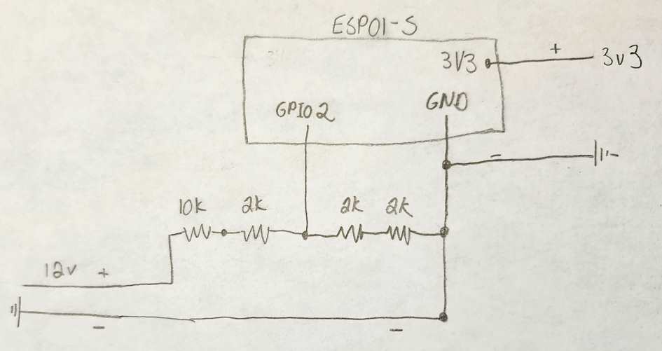
I am using ESP01-S to measure if an external power source is sending me 12V or 0V. I use a voltage divider to drop the voltage down. Here is the circuit (I use a nano in the diagram but in reality it is an ESP01-S)
NOTE: I use an ESP01-S, the real diagram is on a thread below. For this Frizting diagram I use an nano for illustration purposes. In reality on the ESP01-S I use GPIO2. I could not find the ESP01-S for Frizting
If I use a voltmeter at D8 instead of the arduino I get the right voltage and behavior.
If I start my arduino when the external voltage is not 12V but 0V, then the arduino does not boot up. If the power source provides 12V when I start my arduino I get the right behavior, but when I disconnect the external voltage to simulate it giving 0V, the builtin led on the arduino stays on and I get weird behaviors and he code does not execute all the statements (it skips sending me some MQTT message that it shouldn't) ... something is wrong here.
I have a strong feeling I am generating a short somewhere but I cannot see where. I've also tried with a transistor to isolate the external power source voltage (seems overkill) and it also does not work....
all the GND are connected together. I have a feeling this is wrong, but I can't get it to work if they are not connected.
I can build the wiring and post a picture tomorrow ... getting kinda late to whip up my breadboard, but the wiring is really that simple. The only thing that differs is that I use 5k+2k
in serie instead of a 7k since I don't have that resistance on hand...
To add to your graphic, there is no purple wire as the top rail is fed by 3.3v and bottom rail has the external power ranging from 12V to 0V
For context,
This is a signal from my electrical power company. 12V mean I am on a high $kw/h and low means I am paying less for electricity. I want to monitor that state and do other things with the signal, i.e. trigger a relay, send me an e-mail etc. etc...
The fact that it sort of works with the grounds connected should be a clue that maybe that is the correct way of doing it. When you specify a voltage you reference something, the default reference is ground. Electronics is the same way and also needs a reference. The output of your voltage divider is about 2.6V, on the sketchy side for a 3V3 processor and low for a 5V processor. You will not be able to measure that with a digital pin, the best you will get is on or off. To measue you need to use an analog input.
An ESP only has 1 ADC pin and on an ESP-01 it is not exposed.
If you use D8 on an ESP-01 you are connecting to a pin (GPIO 15) which is not exposed.
On an ESP8266 some of the pins need to have a certain state at boot.
GPIO 0, 1 & 2 should not be pulled LOW. GPIO 15 should not be pulled HIGH (the latter is what you may have run into)
I anyway don't think it is the proper way of connecting to a 12v source on a 3.3v MCU. I suggest you use an Opto-coupler to separate and make sure that the inoput never exceeds 3.3v
This is the same circuit without the external power source. The divider is getting power from the digital pin and dropping it to 1.28V and the builtin blue led staying on. Why am I getting this?
You say you connect the thing to D8 but again that's impossible on the ESP-01. D8 is a NodeMCU/WeMOS designation of the pins, in an attempt to be more Arduino Uno like. You're confusing yourself and the forum readers by using those indications, which are not even marked on the ESP-01 as such.
On an ESP-01 you have four pins available: Tx (GPIO 1), Rx (GPIO 3), GPIO 0 and GPIO 2.
Tx has a blue LED connected to it; that will light up when you use it as input and bring the pin high.
Rx has nothing special if you do not use the Serial interface.
GPIO 0 is used in the boot sequence, and must be pulled HIGH for the ESP to boot.
GPIO 2 is used in the boot sequence, and is pulled high internally to boot; pulling it LOW externally (e.g. with your voltage divider) will stop it from booting.
So using either GPIO 0 or GPIO 2 for your voltage detector will stop your device from booting.
Please show a schematic of how you have wired things. No Fritzing wiring diagrams. No "I've used a Nano in the image but it's an ESP" laziness, that's useless and only adds confusion as you've seen already. Just use pen and paper if you don't have real schematic software such as KiCAD (which is free!) at hand.
I admit I used a Nano and I though I would not have to resort to using the ESP01-S diagram. I could not find the frizting ESP01-S part so I resorted to the Nano.
I now wish I have taken the pen an paper route altogether. I really did not want to confuse any kind soul that would want to help out
I will draw the diagram pen & paper style. I also think me using GPIO2 with my voltage divider is the issue.
To note, I just tried the same but with a NodeMCU Lolin v3 wired in and I get the same issue with GPIO2.