Hi everyone,
I am a beginner and I am working on a smartwatch project. I plan to use an esp32-c3 supermini as the main controller with a 1.44' SPI 128X128 ST7735s LCD as the display. I purchased these from the internet.
I have tried a lot of example code based on online tutorials and the display consistently shows only a white backlight. I have checked almost everything on the internet about this and have been unable to solve this problem. I kind of wonder if my display is broken.
Don't hope someone can help you. Instead, provide the information needed so that forum members can help you. Start be reading the forum guide in the sticky post at the top of the forum section.
after installing the Adafruit library open
File>Examples>Adafruit SS7735 and ST7789 Library>graphicstest
then try (note at A0 is DC LCD register / data selection signal)
#else
  // For the breakout board, you can use any 2 or 3 pins.
  // These pins will also work for the 1.8" TFT shield.
  #define TFT_CS        7
  #define TFT_RST        -1 // Or set to -1 and connect to Arduino RESET pin
  #define TFT_DC         6    // is the TFT A0 pin
#endif
connect LED backlight control to 3.3V
VCC is usually controlled by J1
if J1 is open VCC is 5V
if J1 is shorted VCC is 3.3V
the display logic level is always 3.3V
#define TFT_RST -1 // Or set to -1 and connect to Arduino RESET pin
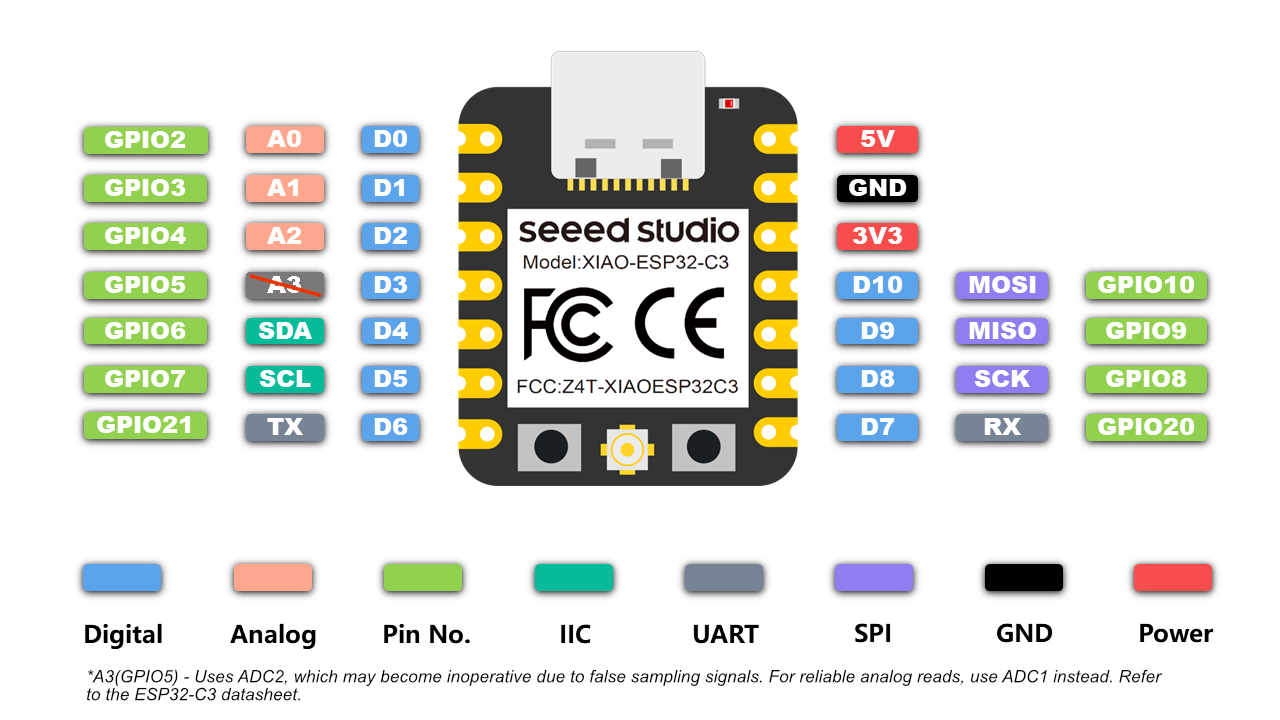
The command says I should connect the RESET pin to the Arduino RESET pin, but it seems that the online pinout, esp32-c3 supermini doesn't have a RESET pin, so I should leave the RESET pin of the screen unused and not connect it anywhere?
I have tried numerous libraries and examples and I cannot get this combination to work at all. I have even spent the last three days with chatgpt trying to help as well and no luck.
But I CAN get this display to work with a esp32-wroom-32 module off amazon, the most widely available esp32 I've seen there. These ones https://a.co/d/b8v1ke5
I have gotten it to work with the bodmer/tft_espi and the bitbank2/animatedgif libraries.
I had to change to edit the User_Setup.h file and make these changes: #define ST7735_DRIVER #define TFT_WIDTH 128 #define TFT_HEIGHT 128 #define ST7735_GREENTAB3
I used pins #define TFT_MOSI 15 // In some display driver board, it might be written as "SDA" and so on. #define TFT_SCLK 14 #define TFT_CS 5 // Chip select control pin #define TFT_DC 27 // Data Command control pin #define TFT_RST 33 // Reset pin (could connect to Arduino RESET pin)
Vcc to 5v
LED to 3v
Gnd to Gnd
I was able to display a animated gif in a loop successfully on the wroom module. But all attempts to use the esp32c3 have failed.
Here is the code I have that worked on the esp32-wroom.
// Display an animated GIF on a 1.44" TFT SPI display via an ESP32

// include the libraries we need
#include <SPI.h>
#include <TFT_eSPI.h>
#include <AnimatedGIF.h>
AnimatedGIF gif;

// KEEP GIF SIZE LOW
// image2c software needed to convert to .h
// 128x128
// GIFDraw.ino also required to be in the same folder

// include the header file we converted the GIF to
#include "sm_red_radar.h"

// pin setup for ESP32 and a 1.44" TFT SPI display
#define SCLK_PIN D8 //14 // SCK
#define MOSI_PIN D10 //15 // SDA
#define DC_PIN   D1 //27 // A0
#define CS_PIN   D0 //5
#define RST_PIN  D2 //33
// #define TFT_BL   22
// #define TFT_BACKLIGHT_ON HIGH  // HIGH or LOW are options

// colors for clearing the screen and as a background
#define BLACK   0x0000
#define BLUE    0x001F
#define RED     0xF800
#define GREEN   0x07E0
#define CYAN    0x07FF
#define MAGENTA 0xF81F
#define YELLOW  0xFFE0
#define WHITE   0xFFFF

// define the name of the GIF, can be found in the header file we created
#define GIF_IMAGE sm_red_radar

// enable DMA mode for faster rendering
#define USE_DMA       // ESP32 ~1.25x single frame rendering performance boost for badgers.h
                      // Note: Do not use SPI DMA if reading GIF images from SPI SD card on same bus as TFT
#define NORMAL_SPEED  // Comment out for frame rate for render speed test

TFT_eSPI tft = TFT_eSPI();

void setup(void) {
  Serial.begin(115200);
  Serial.println("ESP32 is starting up");

  Serial.println("TFT screen initialising");
  tft.begin();

  #ifdef USE_DMA
  tft.initDMA();
  #endif

  tft.fillScreen(BLACK);
  gif.begin(BIG_ENDIAN_PIXELS);

  // uncomment to rotate
  // tft.setRotation(1);
  // use this to clear the screen of previous images
  // tft.fillScreen(BLACK);

  Serial.println("Image has been rendered onto screen");
}

void loop() {
  // Put your main code here, to run repeatedly:

  if (gif.open((uint8_t *)GIF_IMAGE, sizeof(GIF_IMAGE), GIFDraw))
  {
    Serial.printf("Successfully opened GIF; Canvas size = %d x %d\n", gif.getCanvasWidth(), gif.getCanvasHeight());
    tft.startWrite(); // The TFT chip select is locked low
    while (gif.playFrame(true, NULL))
    {
      yield();
    }
    gif.close();
    tft.endWrite(); // Release TFT chip select for other SPI devices
  }

}
I am not sure where to go from here, I have exhausted all of the option I can think of.
which ESP32C3 are you using?
using a ESP32-C3 supermini with a 1_8_inch_ST7735_TFT using the Adafruit-ST7735-Library I defined
// ESP32-C3 supermini  These pins will also work for the 1.8" TFT shield.
  #define TFT_CS         7
  #define TFT_RST        9 // Or set to -1 and connect to Arduino RESET pin
  #define TFT_DC         8
NOTE: test using TFP_eSPI library using same pin settings fails - ESP32C3 throws an exception and starts looping resetting continuously
User_Setup.h file
// TFT_eSPI setup.h file for  ESP32-C3 supermini 1.8 inch_ST7735_TFT
// RP2040 Waveshare General 2inch LCD Display Module IPS Screen 240×320 ST7789

#define USER_SETUP_INFO "User_Setup"

#define ST7735_DRIVER      // Full configuration option, define additional parameters below for this display

#define ST7735_GREENTAB
// For ST7735, ST7789 and ILI9341 ONLY, define the colour order IF the blue and red are swapped on your display
// Try ONE option at a time to find the correct colour order for your display
//  #define TFT_RGB_ORDER TFT_RGB  // Colour order Red-Green-Blue
//  #define TFT_RGB_ORDER TFT_BGR  // Colour order Blue-Green-Red

// For ST7789, ST7735, ILI9163 and GC9A01 ONLY, define the pixel width and height in portrait orientation
#define TFT_WIDTH  128 // ST7789 240 x 240 and 240 x 320
#define TFT_HEIGHT 160 // ST7789 240 x 320

// If colours are inverted (white shows as black) then uncomment one of the next
// 2 lines try both options, one of the options should correct the inversion.

// #define TFT_INVERSION_ON
// #define TFT_INVERSION_OFF

#define TFT_CS   7 //  RESP32-C3-MINI-1 Module
#define TFT_MOSI MOSI
#define TFT_SCLK SCK
#define TFT_MISO MISO

#define TFT_DC   8
#define TFT_RST  9

#define LOAD_GLCD
#define LOAD_FONT2
#define LOAD_FONT4
#define LOAD_FONT6
#define LOAD_FONT7
#define LOAD_FONT8
#define LOAD_GFXFF

#define SMOOTH_FONT

#define SPI_FREQUENCY   10000000

#define SPI_TOUCH_FREQUENCY  2500000
tried different pins for DC and RST - same problem
And I am using the TFT_eSPI library by bodmer. I was able to get the Adafruit libraries/examples to work with this specific ESP32 using the same pins listed below.
It turns out there is a bug in the ESP-core files for the ESP32C3 and S3 variants after version 2.0.14 with the TFT_eSPI library. The bug causes the chips to just reset indefinitely, SPI port issue. The esp32 gets constant guru meditation errors.
The only fix I have found is to roll back ESP32-Core (ESP32 by espressif) to v2.0.14 or earlier in the Arduino IDE. If you are using Platformio you have to use v6.6.0. But even when downgrading ESP32 core in Platformio I still could not get the same code to work, only with the Arduino IDE.
Keep playing around with the correct settings till you get it. I too had the same issue - everything looked white.
funnily enough - there is some weird ghost in my 1.44" 128x128 screen. I was struggling to understand why no SPI data is being fed to it. All the wiring looked right.
But there was no display reset, no image output. I removed the connectors from the breadboard and reconnected and voila! I don't know how to explain that.
I have the waveshare-esp32s3.
The settings I needed are:
(You have to correctly configure the SPI object with your specific pins since ESP32S3 can use any pins for communication over I2C, SPI:
Within Setup(), you must configure the SPI object to use the correct pins like this:
void setup(void) {
  // Init SPI object for HW SPI
  SPI.begin(TFT_CLK, -1, TFT_MOSI, TFT_CS);

  // Backlight control
  pinMode(TFT_BACKLITE, OUTPUT);
  digitalWrite(TFT_BACKLITE, HIGH);
....
 // OR use this initializer (uncomment) if using a 1.44" TFT:
  tft.initR(INITR_144GREENTAB); // Init ST7735R chip, green tab
}