There is something wrong in my code can anyone help me
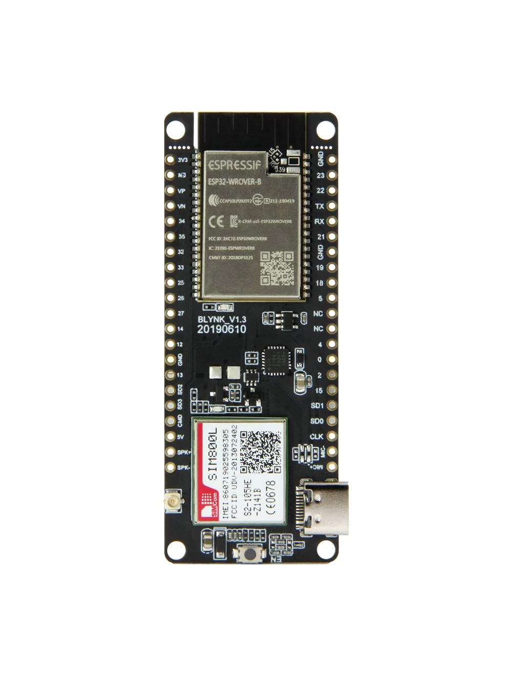
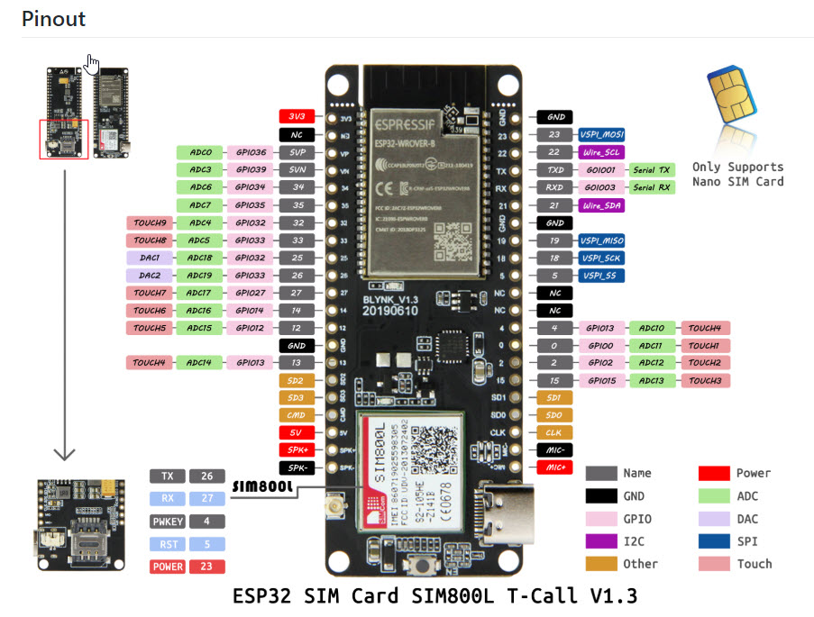
In the code I have used a ttgo tcall module with sim 800l on it so the project is about measuring voltages of 4 gpioo pins and sending the data through sms due to unavailability of internet.
Everything is working just problem is happening in the i2c Part
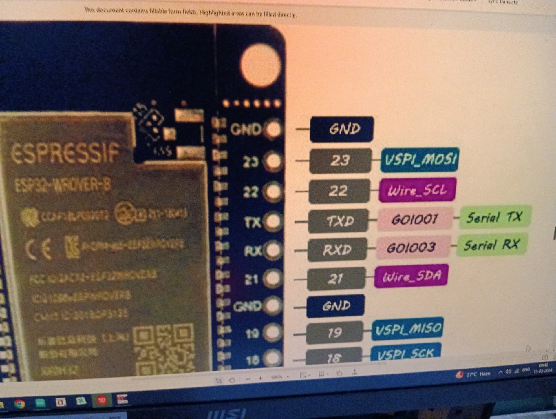
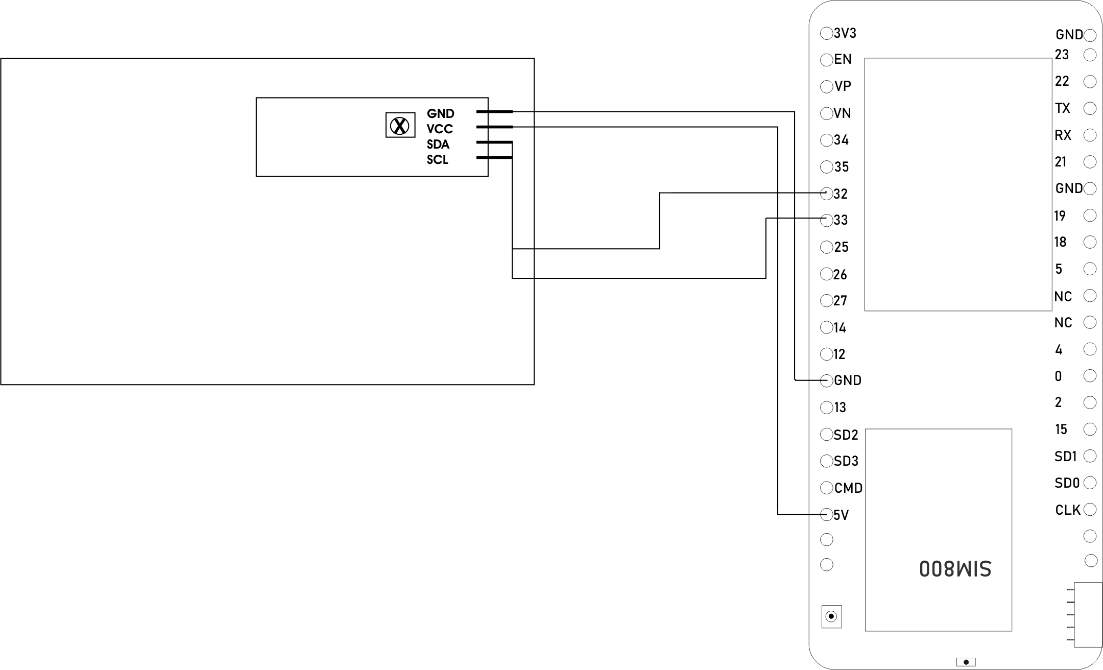
The i2c pins for power management ic ip5306 is set to SDA- 21
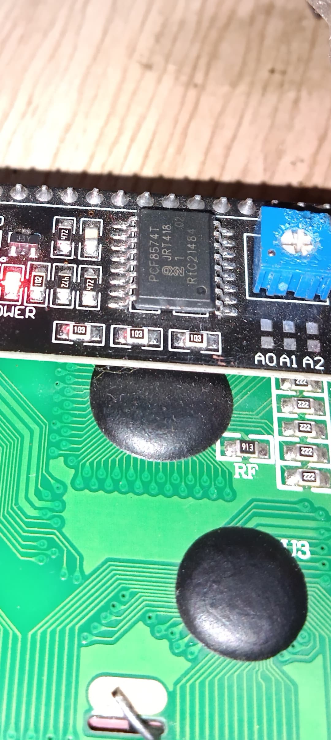
and SCL-22 . And a 20*4 lcd is set to SDA-33 and SCL-32 when I am removing the i2c of ip5306 the lcd works fine and if ip5406 is included lcd stops working . Even the lcd address is 0x26 and the ic is 0x72 still encountering problems . I would be thankful if someone helps me (I am not going to deeper explanations for it would become too long)
const char simPIN[]   = "";

String SMS_Message;
#include <Wire.h>
#include <LiquidCrystal_I2C.h>
// Define the serial console for debug prints, if needed
#define DUMP_AT_COMMANDS

#include<string.h>
#include "utilities.h"

// Configure TinyGSM library
#define TINY_GSM_MODEM_SIM800      // Modem is SIM800
#define TINY_GSM_RX_BUFFER   1024  // Set RX buffer to 1Kb
#include <Wire.h>
#include <TinyGsmClient.h>
// TTGO T-Call pins
#define MODEM_RST            5
#define MODEM_PWKEY          4
#define MODEM_POWER_ON       23
#define MODEM_TX             27
#define MODEM_RX             26
#define RST_PIN 14  // GPIO pin connected to the RST switch
#define SDA_PIN 33  // GPIO pin connected to the SDA pin of the LCD
#define SCL_PIN 32  // GPIO pin connected to the SCL pin of the LCD
#define I2C_SDA              21
#define I2C_SCL              22
#define LCD_ADDRESS 0x27  // I2C address for the LCD
#define LCD_COLS 20
#define LCD_ROWS 4
char* lower = "";
char* response = " ";
String res = "";
bool new_data = 0;
int relay = 0;

#define SMS_TARGET_1  "+919836556923"
#define SMS_TARGET_2  "+919333004309"
#define SMS_TARGET_3 "+919433103566"
char* msg = "+cmt: \"+919433103566\"";
char* msg2 = "+cmt: \"+919836556923\"";
char* msg3 = "+cmt: \"+919333004309\"";

char* ring = "+clip: \"+919836556923\"";


char* value1 = "SEND";
char* value0 = "GETNET";


// Set serial for debug console (to Serial Monitor, default speed 115200)
#define SerialMon Serial
// Set serial for AT commands (to SIM800 module)
#define SerialAT  Serial1
// Define the serial console for debug prints, if needed
//#define DUMP_AT_COMMANDS
#ifdef DUMP_AT_COMMANDS
#include <StreamDebugger.h>
StreamDebugger debugger(SerialAT, SerialMon);
TinyGsm modem(debugger);
#else
TinyGsm modem(SerialAT);
#endif
#include <LiquidCrystal_I2C.h>
LiquidCrystal_I2C lcd(LCD_ADDRESS, LCD_COLS, LCD_ROWS);  // Address of the I2C module may vary, use i2c scanner to find it

const int voltagePinA = 2;   // Analog input pin for voltage A measurement
const int voltagePinB = 0;   // Analog input pin for voltage B measurement (GPI00)
const int voltagePinC = 4;   // Analog input pin for voltage C measurement (GPI02)
const int voltagePinD = 15;  // Analog input pin for voltage D measurement (GPI015)

unsigned long previousMillis = 0;
const long interval = 60000*60;  // Interval to measure voltages (60 seconds)

int mode = 1; // Default mode is 1
bool displayMeasurements = true;  // Flag to indicate whether to display measurements or "Mode 2"
void updateSerial();
// I2C for SIM800 (to keep it running when powered from battery)
TwoWire I2CPower = TwoWire(0);


#define uS_TO_S_FACTOR 1000000UL   /* Conversion factor for micro seconds to seconds */


#define IP5306_ADDR          0x75
#define IP5306_REG_SYS_CTL0  0x00

bool setPowerBoostKeepOn(int en){
  I2CPower.beginTransmission(IP5306_ADDR);
  I2CPower.write(IP5306_REG_SYS_CTL0);
  if (en) {
    I2CPower.write(0x37); // Set bit1: 1 enable 0 disable boost keep on
  } else {
    I2CPower.write(0x35); // 0x37 is default reg value
  }
  return I2CPower.endTransmission() == 0;
}


void setup() {
    // Your setup code here
    {
  Serial.begin(115200);
    I2CPower.begin(I2C_SDA, I2C_SCL, 400000);
  // Keep power when running from battery


  // Keep power when running from battery
  bool isOk = setPowerBoostKeepOn(0);
  SerialMon.println(String("IP5306 KeepOn ") + (isOk ? "OK" : "FAIL"));


  // Set modem reset, enable, power pins
  pinMode(MODEM_PWKEY, OUTPUT);
  pinMode(MODEM_RST, OUTPUT);
  pinMode(MODEM_POWER_ON, OUTPUT);
  digitalWrite(MODEM_PWKEY, LOW);
  digitalWrite(MODEM_RST, HIGH);
  digitalWrite(MODEM_POWER_ON, HIGH);
///////////////////////////////////////////////////
  // LCD setup
  lcd.begin(LCD_COLS, LCD_ROWS);  // Initialize the LCD
  lcd.backlight();
  lcd.setCursor(0, 0);
  lcd.print("Voltage A : -");
  lcd.setCursor(0, 1);
  lcd.print("Voltage B : -");
  lcd.setCursor(0, 2);
  lcd.print("Voltage C : -");
  lcd.setCursor(0, 3);
  lcd.print("Voltage D : -");
  /////////////////////////////////////////////////
  // Set GSM module baud rate and UART pins
  SerialAT.begin(115200, SERIAL_8N1, MODEM_RX, MODEM_TX);
  delay(3000);
  // Restart SIM800 module, it takes quite some time
  // To skip it, call init() instead of restart()
  SerialMon.println("Initializing modem...");
  modem.restart();
  // use modem.init() if you don't need the complete restart
  // Unlock your SIM card with a PIN if needed
  if (strlen(simPIN) && modem.getSimStatus() != 3 ) {
    modem.simUnlock(simPIN);
      String modemInfo = modem.getModemInfo();
  SerialMon.print("Modem Info: ");
  SerialMon.println(modemInfo);
  delay(1000);

  SerialAT.println("AT"); //Once the handshake test is successful, it will back to OK
  updateSerial();

  SerialAT.println("AT+CMGF=1"); // Configuring TEXT mode
  updateSerial();
  SerialAT.println("AT+CNMI=1,2,0,0,0"); // Decides how newly arrived SMS messages should be handled
  updateSerial();
  }

    // Measure voltage A
    int sensorValueA = analogRead(voltagePinA);
    float voltageA = sensorValueA * (3.3 / 4095.0);  // Assuming ESP32 ADC is 12-bit

    // Measure voltage B
    int sensorValueB = analogRead(voltagePinB);
    float voltageB = sensorValueB * (3.3 / 4095.0);

    // Measure voltage C
    int sensorValueC = analogRead(voltagePinC);
    float voltageC = sensorValueC * (3.3 / 4095.0);

    // Measure voltage D
    int sensorValueD = analogRead(voltagePinD);
    float voltageD = sensorValueD * (3.3 / 4095.0);

    // Display voltages on LCD
    lcd.setCursor(0, 0);
    lcd.print("Voltage A : -");
    lcd.print(String(voltageA, 3) + "V");

    lcd.setCursor(0, 1);
    lcd.print("Voltage B : -");
    lcd.print(String(voltageB, 3) + "V");

    lcd.setCursor(0, 2);
    lcd.print("Voltage C : -");
    lcd.print(String(voltageC, 3) + "V");

    lcd.setCursor(0, 3);
    lcd.print("Voltage D : -");
    lcd.print(String(voltageD, 3) + "V");

    // Display voltages on Serial Monitor
    Serial.print("Voltage A : -");
    Serial.print(voltageA, 3);
    Serial.println("V");

    Serial.print("Voltage B : -");
    Serial.print(voltageB, 3);
    Serial.println("V");

    Serial.print("Voltage C : -");
    Serial.print(voltageC, 3);
    Serial.println("V");

    Serial.print("Voltage D : -");
    Serial.print(voltageD, 3);
    Serial.println("V");