Hello, you guys are my last hope. Im using an ESP32 board (a DOIT ESP32 DEVKIT V1 clone) with an I2C LCD module (20x4). i tried, i think, everything to make the ESP32 detect/connect to the LCD module. I tried the script for my project, i tried multiple I2C scanner and a script to even know if the ESP32 is able to connect to I2C. trust me, all the connection are good, strong solder. the VCC of the module is connected to an external 5v supply as i need the Vin pin to be connected to the same 5v supply (its a stable 5v). i tried connecting the GND both to the “power supply” and to the board, the only difference is when its connected to the power supply, the screen light up, when connected to the ESP32, the screen dont light up. the SDA is connected to the GPIO 21 and the SCL to the GPIO 22 as it need to be on my board (and the ESP32 is for now powered by USB. the power supply for the circuit is active). so yeah, im pretty lost right now. here is the error message i get with the - connected to the GND of the board:
E (6013) i2c.master: probe device timeout. Please check if xfer_timeout_ms and pull-ups are correctly set up
and here it is with the - connected to the - of the power-supply:
E (10269) i2c.master: s_i2c_synchronous_transaction(945): I2C transaction failed E (10276) i2c.master: i2c_master_multi_buffer_transmit(1214): I2C transaction failed E (10286) i2c.master: I2C hardware timeout detected
So post a link to your LCD and some wiring scheme how it's wired/supplied. 5V supply to some device connected to (3.3V) Esp32 is often something to be investigated.
Without common GND between Esp and LCD there's no hope..
here’s a heads up: the pinout diagram for the T Beam has the SDA and SCL pins reversed on the call out. if you look at the board the numbers are right. the large easy to read rectangles are wrong. try reversing the SDA and SCL pins
i am too much bad at making electrical schematic. so i will try to explain it better (only the part that interest us: not the sensor part as it as nothing to do with this.
Battery (2 18650) switch buck down (7.4v to 5v, voltage is ok as i checked it with my multimeter) VCC LCD screen GND of the ESP32 USB-C cable connected to my pc. the ESP32 have for power source, for now, the USB cable. in the future, the buck down will be connected to the ESP32.
i just tried the example code of i2c scan for the Wire and… it found a device at all I2C address possible. what? no error code tho.
nop talk to soon, i just realise there was this error code:
E (26799) i2c.master: I2C transaction timeout detected
E (26799) i2c.master: probe device timeout. Please check if xfer_timeout_ms and pull-ups are correctly set up
Error 5 at address 0x4C
E (26812) i2c.master: I2C hardware timeout detected
E (26812) i2c.master: probe device timeout. Please check if xfer_timeout_ms and pull-ups are correctly set up
// SPDX-FileCopyrightText: 2023 Carter Nelson for Adafruit Industries
//
// SPDX-License-Identifier: MIT
// --------------------------------------
// i2c_scanner
//
// Modified from https://playground.arduino.cc/Main/I2cScanner/
// --------------------------------------

#include <Wire.h>

// Set I2C bus to use: Wire, Wire1, etc.
#define WIRE Wire

void setup() {
  WIRE.begin();

  Serial.begin(9600);
  while (!Serial)
     delay(10);
  Serial.println("\nI2C Scanner");
}


void loop() {
  byte error, address;
  int nDevices;

  Serial.println("Scanning...");

  nDevices = 0;
  for(address = 1; address < 127; address++ )
  {
    // The i2c_scanner uses the return value of
    // the Write.endTransmisstion to see if
    // a device did acknowledge to the address.
    WIRE.beginTransmission(address);
    error = WIRE.endTransmission();

    if (error == 0)
    {
      Serial.print("I2C device found at address 0x");
      if (address<16)
        Serial.print("0");
      Serial.print(address,HEX);
      Serial.println("  !");

      nDevices++;
    }
    else if (error==4)
    {
      Serial.print("Unknown error at address 0x");
      if (address<16)
        Serial.print("0");
      Serial.println(address,HEX);
    }
  }
  if (nDevices == 0)
    Serial.println("No I2C devices found\n");
  else
    Serial.println("done\n");

  delay(5000);           // wait 5 seconds for next scan
}
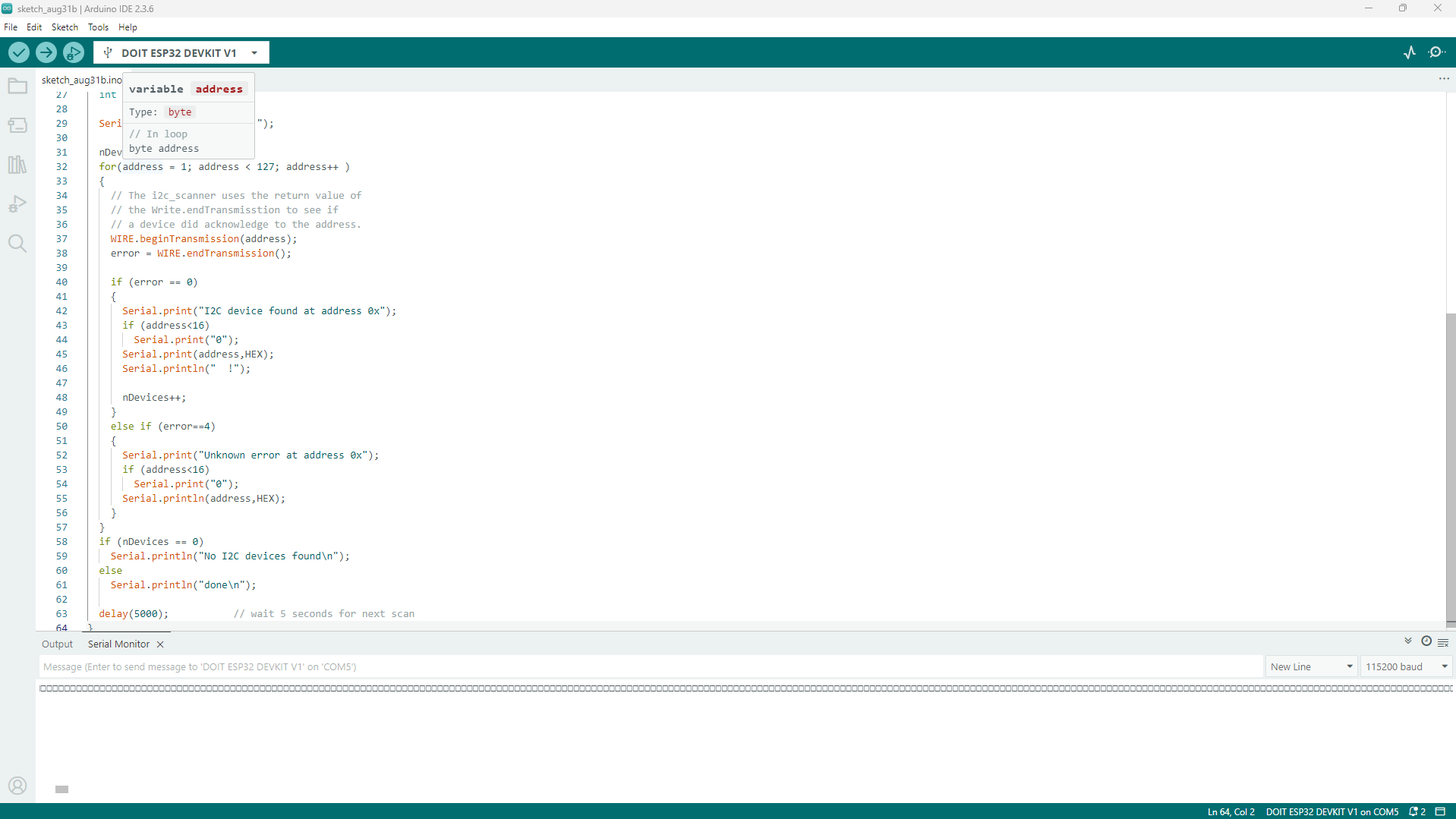
but with the wirescan (example code), i get this (only showing a little part as i cant copy-paste it all for some reason):
I2C device found at address 0x21
I2C device found at address 0x22
I2C device found at address 0x23
I2C device found at address 0x24
I2C device found at address 0x25
I2C device found at address 0x26
I2C device found at address 0x27
I2C device found at address 0x28
I2C device found at address 0x29
I2C device found at address 0x2A
I2C device found at address 0x2B
I2C device found at address 0x2C
I2C device found at address 0x2D
I2C device found at address 0x2E
I2C device found at address 0x2F
I2C device found at address 0x30
E (31973) i2c.master: I2C transaction timeout detected
E (31973) i2c.master: probe device timeout. Please check if xfer_timeout_ms and pull-ups are correctly set up
Error 5 at address 0x31
E (31987) i2c.master: I2C hardware timeout detected
E (31987) i2c.master: probe device timeout. Please check if xfer_timeout_ms and pull-ups are correctly set up
Error 5 at address 0x32
I2C device found at address 0x33
I2C device found at address 0x34
I2C device found at address 0x35
I2C device found at address 0x36
I2C device found at address 0x37
I2C device found at address 0x38
I2C device found at address 0x39
I2C device found at address 0x3A
I2C device found at address 0x3B
I2C device found at address 0x3C
I2C device found at address 0x3D
I2C device found at address 0x3E
I2C device found at address 0x3F
This is what I see. I have no devices plugged in so it is correct.
The software you are using is not correct.
If you want help you need to follow the instructions given and not go off on your own.
Lets start over
3- this is as best as i can give you. thanks to Geek_Emeritus, the I2C cable might be connected the right way now. so this is the power diagram: Battery (2 18650) switch buck down (7.4v to 5v, voltage is ok as i checked it with my multimeter) VCC LCD screen GND of the ESP32 USB-C cable connected to my pc. the ESP32 have for power source, for now, the USB cable.
4- well, its exactly what i sent above. those little rectangle in the screenshot? thats the result!
Until you load a skecth that writes to the screen you will not see anything but first you need to get the correct answer from the I2C scanner, have you done that if so show me.