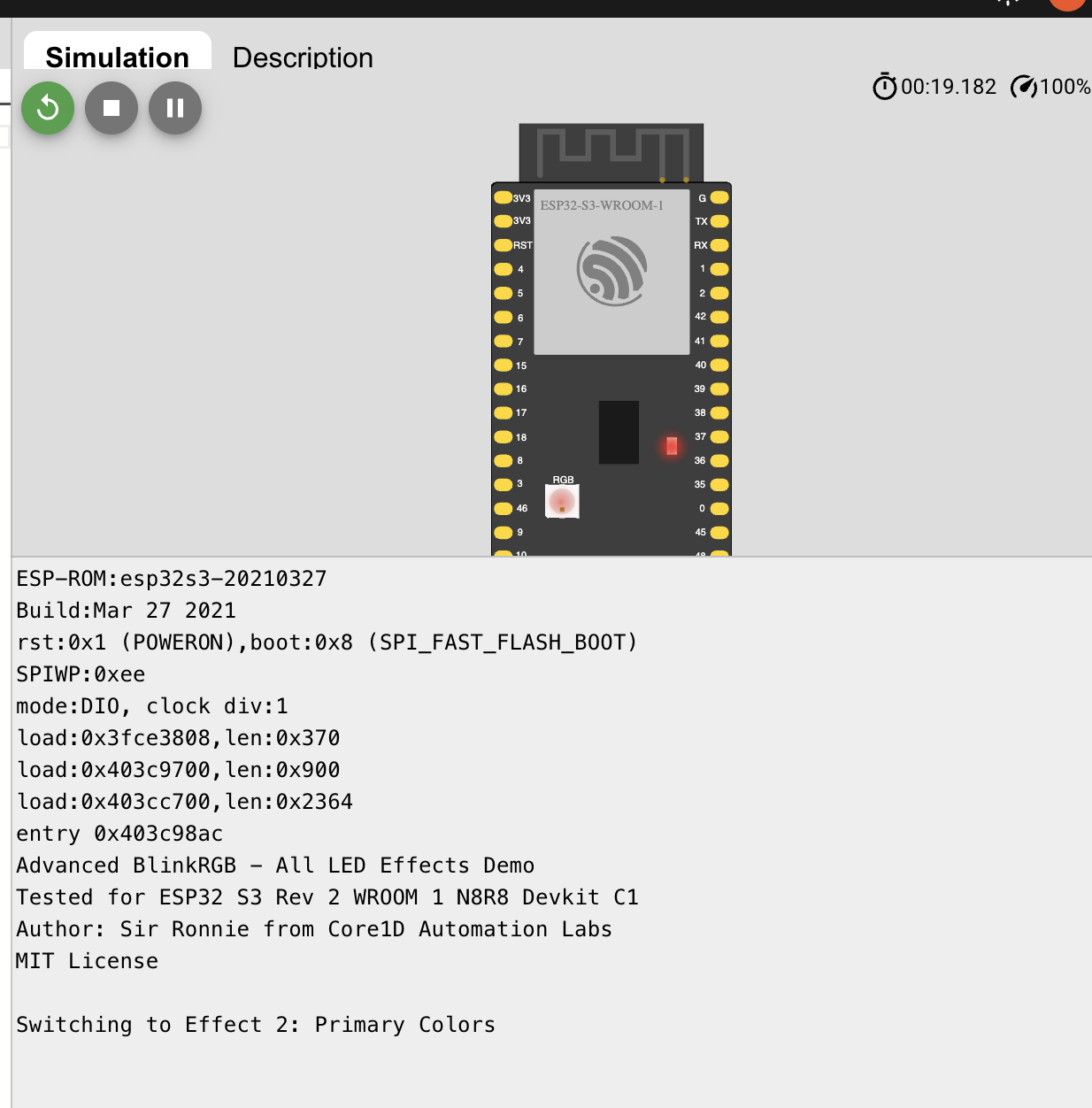
An Arduino IDE sketch written and tested for ESP32 S3 Devkit C1, which has an RGB led on board connected to GPIO38.
Based on the BlinkRGB.ino example sketch for Arduino IDE by Espressif Systems.
Make sure you are well aware of the board and build (no harm in double checking. It is a good habit in this field).
If you have ESP32 S3 WROOM1 N8R8 Devkit C1 board, you can refer to this link to verify your setup with Arduino IDE, where I provide information from my bit of the experience.
ESP32 S3 Devkit C1 Arduino IDE Sanity Check
BlinkRGBAdv.ino
/*
  BlinkRGB Example Sketch Revision 2 - Advanced LED Effects
  Improved ESP32 Blink RGB sketch.

  Demonstrates comprehensive usage of onboard RGB LED on ESP32 dev boards.

  Calling digitalWrite(RGB_BUILTIN, HIGH) will use hidden RGB driver.

  RGBLedWrite demonstrates control of each channel:
  void rgbLedWrite(uint8_t pin, uint8_t red_val, uint8_t green_val, uint8_t blue_val)

  WARNING: Do keep in mind that GPIO38 will be inaccessible/locked if RGB LED is used. (Typical for any extra board components).

  Tested for: ESP32 S3 Rev2 WROOM1 N8R8 Devkit C1
  Designed by: Sir Ronnie from Core1D Automation Labs
  Based on ESP32 BlinkRGB.ino example sketch by Espressif Systems
  MIT License.

  Hardware Configuration:
  - RGB LED connected to GPIO 38 (as marked RGB@IO38 on silkscreen)
  - Auto-cycles through effects every 10.24 seconds (optimized for hardware timing)
*/

#define RGB_BUILTIN     38       // Board-specific: RGB LED on GPIO 38
#define RGB_BRIGHTNESS  32      // Default brightness (max 255)
#define EFFECT_DURATION 10240  // 10.24 seconds per effect (power of 2 for efficiency)
#define FAST_DELAY      50    // Fast transitions
#define MEDIUM_DELAY    100  // Medium transitions
#define SLOW_DELAY      200 // Slow transitions

// Effect counter
      int currentEffect = 0;
const int totalEffects  = 12;

// Global variables for smooth transitions
unsigned long effectStartTime = 0;
          int stepCounter     = 0;

void setup() {
  Serial.begin(115200);
  Serial.println("Advanced BlinkRGB - All LED Effects Demo");
  Serial.println("Tested for ESP32 S3 Rev 2 WROOM 1 N8R8 Devkit C1");
  Serial.println("Enhanced by: Sir Ronnie from Core1D Automation Labs");
  Serial.println("MIT License\n");

  effectStartTime = millis();
}

void loop() {
  // Check if it's time to switch to next effect
  if (millis() - effectStartTime >= EFFECT_DURATION) {
    currentEffect   = (currentEffect + 1) % totalEffects;
    effectStartTime = millis();
    stepCounter     = 0;
    Serial.print("Switching to Effect ");
    Serial.print(currentEffect + 1);
    Serial.print(": ");
    printEffectName(currentEffect);
    Serial.println();
  }

  // Execute current effect
  switch (currentEffect) {
    case  0: basicOnOff();       break;
    case  1: primaryColors();    break;
    case  2: rainbowCycle();     break;
    case  3: breathingEffect();  break;
    case  4: strobeEffect();     break;
    case  5: colorFade();        break;
    case  6: randomColors();     break;
    case  7: fireEffect();       break;
    case  8: policeFlasher();    break;
    case  9: heartbeat();        break;
    case 10: matrixEffect();     break;
    case 11: spectrumAnalyzer(); break;
  }
}

void printEffectName(int effect) {
  const char* names[] = {
    "Basic On/Off",   "Primary Colors", "Rainbow Cycle", "Breathing Effect",
    "Strobe Effect",  "Color Fade",     "Random Colors", "Fire Effect",
    "Police Flasher", "Heartbeat",      "Matrix Effect", "Spectrum Analyzer"
  };
  Serial.print(names[effect]);
}

// Effect 1: Basic On/Off (Original functionality)
void basicOnOff() {
  digitalWrite(RGB_BUILTIN, HIGH);  // White
  delay(1000);
  digitalWrite(RGB_BUILTIN, LOW);   // Off
  delay(1000);
}

// Effect 2: Primary Colors
void primaryColors() {
  rgbLedWrite(RGB_BUILTIN, RGB_BRIGHTNESS, 0,              0);               // Red
  delay(800);
  rgbLedWrite(RGB_BUILTIN, 0,              RGB_BRIGHTNESS, 0);               // Green
  delay(800);
  rgbLedWrite(RGB_BUILTIN, 0,              0,              RGB_BRIGHTNESS);  // Blue
  delay(800);
  rgbLedWrite(RGB_BUILTIN, RGB_BRIGHTNESS, RGB_BRIGHTNESS, 0);               // Yellow
  delay(800);
  rgbLedWrite(RGB_BUILTIN, RGB_BRIGHTNESS, 0,              RGB_BRIGHTNESS);  // Magenta
  delay(800);
  rgbLedWrite(RGB_BUILTIN, 0,              RGB_BRIGHTNESS, RGB_BRIGHTNESS);  // Cyan
  delay(800);
  rgbLedWrite(RGB_BUILTIN, RGB_BRIGHTNESS, RGB_BRIGHTNESS, RGB_BRIGHTNESS);  // White
  delay(800);
  rgbLedWrite(RGB_BUILTIN, 0,              0,              0);               // Off
  delay(800);
}

// Effect 3: Rainbow Cycle
void rainbowCycle() {
  static int hue = 0;
  int r, g, b;
  hsvToRgb(hue, 255, RGB_BRIGHTNESS, &r, &g, &b);
  rgbLedWrite(RGB_BUILTIN, r, g, b);
  hue = (hue + 2) % 360;
  delay(FAST_DELAY);
}

// Effect 4: Breathing Effect
void breathingEffect() {
  static bool increasing = true;
  static int brightness  = 0;

  if (increasing) {
    brightness += 2;
    if (brightness >= RGB_BRIGHTNESS) increasing = false;
  } else {
    brightness -= 2;
    if (brightness <= 0) increasing = true;
  }

  rgbLedWrite(RGB_BUILTIN, 0, brightness, brightness/2);  // Cyan breathing
  delay(30);
}

// Effect 5: Strobe Effect
void strobeEffect() {
  for (int flash = 0; flash < 10; flash++) {
    rgbLedWrite(RGB_BUILTIN, RGB_BRIGHTNESS, RGB_BRIGHTNESS, RGB_BRIGHTNESS);
    delay(50);
    rgbLedWrite(RGB_BUILTIN, 0, 0, 0);
    delay(50);
  }
  delay(500);
}

// Effect 6: Color Fade Transitions
void colorFade() {
  static int phase     = 0;
  static int fadeValue = 0;
  static bool fadeUp   = true;

  int r = 0, g = 0, b = 0;

  switch (phase) {
    case 0: r = fadeValue;                                                  break; // Red fade in
    case 1: r = RGB_BRIGHTNESS;             g = fadeValue;                  break; // Green fade in
    case 2: r = RGB_BRIGHTNESS - fadeValue; g = RGB_BRIGHTNESS;             break; // Red fade out
    case 3: g = RGB_BRIGHTNESS;             b = fadeValue;                  break; // Blue fade in
    case 4: g = RGB_BRIGHTNESS - fadeValue; b = RGB_BRIGHTNESS;             break; // Green fade out
    case 5: r = fadeValue;                  b = RGB_BRIGHTNESS;             break; // Red fade in
    case 6: r = RGB_BRIGHTNESS;             b = RGB_BRIGHTNESS - fadeValue; break; // Blue fade out
  }

  rgbLedWrite(RGB_BUILTIN, r, g, b);

  if (fadeUp) {
    fadeValue += 4;
    if (fadeValue >= RGB_BRIGHTNESS) {
      fadeUp = false;
      phase = (phase + 1) % 7;
    }
  } else {
    fadeValue -= 4;
    if (fadeValue <= 0) fadeUp = true;
  }

  delay(30);
}

// Effect 7: Random Colors
void randomColors() {
  int r = random(0, RGB_BRIGHTNESS + 1);
  int g = random(0, RGB_BRIGHTNESS + 1);
  int b = random(0, RGB_BRIGHTNESS + 1);
  rgbLedWrite(RGB_BUILTIN, r, g, b);
  delay(300);
}

// Effect 8: Fire Effect
void fireEffect() {
  int red   = RGB_BRIGHTNESS;
  int green = random(0, RGB_BRIGHTNESS/2);
  int blue  = random(0, RGB_BRIGHTNESS/8);
  rgbLedWrite(RGB_BUILTIN, red, green, blue);
  delay(random(50, 150));
}

// Effect 9: Police Flasher
void policeFlasher() {
  // Red flash
  for (int i = 0; i < 3; i++) {
    rgbLedWrite(RGB_BUILTIN, RGB_BRIGHTNESS, 0, 0);
    delay(100);
    rgbLedWrite(RGB_BUILTIN, 0, 0, 0);
    delay(100);
  }
  delay(200);

  // Blue flash
  for (int i = 0; i < 3; i++) {
    rgbLedWrite(RGB_BUILTIN, 0, 0, RGB_BRIGHTNESS);
    delay(100);
    rgbLedWrite(RGB_BUILTIN, 0, 0, 0);
    delay(100);
  }
  delay(200);
}

// Effect 10: Heartbeat
void heartbeat() {
  // First beat
  for (int i = 0; i < RGB_BRIGHTNESS; i += 8) {
    rgbLedWrite(RGB_BUILTIN, i, 0, 0);
    delay(10);
  }
  for (int i = RGB_BRIGHTNESS; i >= 0; i -= 8) {
    rgbLedWrite(RGB_BUILTIN, i, 0, 0);
    delay(10);
  }

  delay(100);

  // Second beat
  for (int i = 0; i < RGB_BRIGHTNESS; i += 8) {
    rgbLedWrite(RGB_BUILTIN, i, 0, 0);
    delay(10);
  }
  for (int i = RGB_BRIGHTNESS; i >= 0; i -= 8) {
    rgbLedWrite(RGB_BUILTIN, i, 0, 0);
    delay(10);
  }

  delay(800); // Long pause like heartbeat
}

// Effect 11: Matrix Effect (Green digital rain simulation)
void matrixEffect() {
  static int intensity  = 0;
  static bool direction = true;

  if (direction) {
    intensity += 3;
    if (intensity >= RGB_BRIGHTNESS) direction = false;
  } else {
    intensity -= 3;
    if (intensity <= 0) direction = true;
  }

  // Random green flickers
  if (random(0, 10) > 7) {
    rgbLedWrite(RGB_BUILTIN, 0, random(RGB_BRIGHTNESS/2, RGB_BRIGHTNESS), 0);
  } else {
    rgbLedWrite(RGB_BUILTIN, 0, intensity, 0);
  }
  delay(80);
}

// Effect 12: Spectrum Analyzer Simulation
void spectrumAnalyzer() {
  static int band = 0;
  int colors[][3] = {
    {RGB_BRIGHTNESS, 0, 0},           // Red (bass)
    {RGB_BRIGHTNESS, RGB_BRIGHTNESS/2, 0}, // Orange
    {RGB_BRIGHTNESS, RGB_BRIGHTNESS, 0},   // Yellow
    {0, RGB_BRIGHTNESS, 0},           // Green (mid)
    {0, RGB_BRIGHTNESS, RGB_BRIGHTNESS},   // Cyan
    {0, 0, RGB_BRIGHTNESS},           // Blue (treble)
    {RGB_BRIGHTNESS/2, 0, RGB_BRIGHTNESS}  // Purple
  };

  int level = random(RGB_BRIGHTNESS/4, RGB_BRIGHTNESS);
  rgbLedWrite(RGB_BUILTIN,
              (colors[band][0] * level) / RGB_BRIGHTNESS,
              (colors[band][1] * level) / RGB_BRIGHTNESS,
              (colors[band][2] * level) / RGB_BRIGHTNESS);

  band = (band + 1) % 7;
  delay(150);
}

// Utility function: Convert HSV to RGB
void hsvToRgb(int h, int s, int v, int* r, int* g, int* b) {
  int c = (v * s) / 255;
  int x = (c * (60 - abs((h / 60) % 2 * 60 - 60))) / 60;
  int m = v - c;

  if (h < 60) {
    *r = c; *g = x; *b = 0;
  } else if (h < 120) {
    *r = x; *g = c; *b = 0;
  } else if (h < 180) {
    *r = 0; *g = c; *b = x;
  } else if (h < 240) {
    *r = 0; *g = x; *b = c;
  } else if (h < 300) {
    *r = x; *g = 0; *b = c;
  } else {
    *r = c; *g = 0; *b = x;
  }

  *r += m; *g += m; *b += m;
}