ESP32 Wifi not working when powered by battery

Hello everyone,

I'm quite new to ESP32 development. I've been using this devkit for a few small projects and everything was going smoothly until I decided to run it on battery. In particular, the ESP32 devkit I'm using, when connected to a battery, seems to have issues when trying to connect to the Wifi.

I'm using a 9V battery connected to a MB-V2 power supply to convert the output voltage to 3.3.V. The power supply board has the following specifics:

  • Input voltage: 6.5-9v (DC) via 5.5mm x 2.1mm plug
  • Output voltage: 3.3V/5v
  • Maximum output current: 700 mA
  • Independent control rail output: 0v, 3.3v, 5v to breadboard

As you can see in the picture, my multimeter measures an output voltage of about 3.3V

I built a sample project for debugging, here's the schematics:


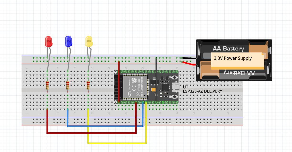
The battery is connected to the power supply which outputs 3.3V and powers the ESP32 through its 3.3V pin. I don't have a schematic for this specific devkit I'm using so the devkit used in the schematics is the DOIT one, hence all of the pins are off. The code is quite simple, though, so it hopefully can clear things a bit:

#include <WiFi.h>

const int uS_TO_S_FACTOR = 1000000;
const int TIME_TO_SLEEP = 3;
const int RED_LED_PIN = 32;
const int BLUE_LED_PIN = 25;
const int YELLOW_LED_PIN = 26;
const char SSID[] = "SSID";
const char PASS[] = "PASS";

void startupSequence(){
  digitalWrite(RED_LED_PIN, LOW);
  digitalWrite(BLUE_LED_PIN, LOW);
  digitalWrite(YELLOW_LED_PIN, LOW);
  // Sequence
  digitalWrite(RED_LED_PIN, HIGH);
  digitalWrite(BLUE_LED_PIN, HIGH);
  digitalWrite(YELLOW_LED_PIN, HIGH);
  delay(1000);
  digitalWrite(RED_LED_PIN, LOW);
  digitalWrite(BLUE_LED_PIN, LOW);
  digitalWrite(YELLOW_LED_PIN, LOW);
  delay(500);
}

void setup(){
  Serial.begin(115200);
  while(!Serial){}
  pinMode(RED_LED_PIN, OUTPUT);
  pinMode(BLUE_LED_PIN, OUTPUT);
  pinMode(YELLOW_LED_PIN, OUTPUT);
  startupSequence();
  delay(500);
  digitalWrite(RED_LED_PIN, HIGH);
  delay(1000);
  Serial.print("Connecting to ");
  Serial.println(SSID);
  WiFi.begin(SSID, PASS);  
  while ((WiFi.status() != WL_CONNECTED) && (millis()<10000)) {
      Serial.print(".");
      delay(500);
  }
  Serial.print("Connected. IP: ");
  Serial.println(WiFi.localIP());
  digitalWrite(RED_LED_PIN, LOW);
  if(WiFi.status() == WL_CONNECTED) //Run this only the first time
  {
    Serial.println("Connected");
    digitalWrite(YELLOW_LED_PIN, HIGH);
  } else
  {
    Serial.println("Not connected");
    digitalWrite(BLUE_LED_PIN, HIGH);
  }
  delay(3000);
  digitalWrite(BLUE_LED_PIN, LOW);
  digitalWrite(YELLOW_LED_PIN, LOW);
  Serial.println("Going to sleep");
  esp_sleep_enable_timer_wakeup(TIME_TO_SLEEP * uS_TO_S_FACTOR);
  esp_deep_sleep_start();
}

void loop(){}

In the code, the ESP32 first lights up all LEDs, then it lights up the red LED while it tries to connect to the Wifi. After at most 10 secs, it lights up the yellow LED if it successfully connected, otherwise it lights up the blue LED. Also, as a last thing I send the ESP32 into deep sleep, as my intention was to measure its power consumption during sleep.

When connected to the PC, everything runs smoothly, while when connected to the battery the ESP32 (apparently) never exits the while loop and the red LED stays always on. The RED led then starts flickering and the power LED start blinking. Resetting it throught the RST button on the devkit causes the power LED to start blinking and the red LED never lights up. This continues until I cut off the power, then the code seems to start again from the beginning (i.e. the startup sequence) and the this behavior repeats.

I've read a few posts about similar issues with ESP32 devkits, but the problem was always about batteries not having high enough voltage, which doesn't seem to be my case. What could be causing the issue?

That PP3 battery is going to last no time at all when supplying the required current to your project. Have you measured the battery and supply voltages under load ?

Your topic was MOVED to its current forum category as it is more suitable than the original

It would probably work with 5 V on the 5 V pin. Battery life would be even shorter.

PP3 and Wifi..... The PP3 is not based on nuclear capacity....

Thanks for answering! I am aware that the battery won't hold for long, but I figure I could use it at least for testing the full project. This is the first time for me using a battery to power a project, so I've no idea of what I could be doing wrong.

I can't test the load when connected to the Wifi, since the code won't run, so I tried measuring the load for this simple code

const int RED_LED_PIN = 32;
const int BLUE_LED_PIN = 25;
const int YELLOW_LED_PIN = 26;

void startupSequence(){
  Serial.println("Startup");
  digitalWrite(RED_LED_PIN, LOW);
  digitalWrite(BLUE_LED_PIN, LOW);
  digitalWrite(YELLOW_LED_PIN, LOW);
  // Sequence
  digitalWrite(RED_LED_PIN, HIGH);
  digitalWrite(BLUE_LED_PIN, HIGH);
  digitalWrite(YELLOW_LED_PIN, HIGH);
  delay(1000);
  digitalWrite(RED_LED_PIN, LOW);
  digitalWrite(BLUE_LED_PIN, LOW);
  digitalWrite(YELLOW_LED_PIN, LOW);
  delay(500);
}

void setup(){
  Serial.begin(115200);
  while(!Serial){}
  pinMode(RED_LED_PIN, OUTPUT);
  pinMode(BLUE_LED_PIN, OUTPUT);
  pinMode(YELLOW_LED_PIN, OUTPUT);
}

void loop(){
  startupSequence();
  delay(500);
}

I then inserted my multimeter between the power supply and the board, in order to measure voltage and current, here the outcomes:

Voltage (under load): 3.3V
Current (under load): 48-53 mA (oscillates)

Which battery would you suggest?

For a quick and dirty 9V, six AA cells are quite powerful.

1 Like

A quick way to power an ESP32 board is to connect a cellphone charger
or powerbank to the USB socket.
Leo..

1 Like

I'll try and report back

Several replies have been given. Consider the setup, the devices used and check the need for power for each of them. Then decide.
There's no easy powering being perfect for all kinds of experiments.
All transmitting devices consumes quite some current but a few single LEDs needs very little current.
Using Wifi there's a transmitter involved.
6AA? For how long time do You want the project to run before reloading?

I would like to go at least 3-4 weeks without reloading. I've yet to measure the power consumption under load with the Wifi working, but the problem is that the only devices that I got that can power the Wifi use a USB cable and I've no idea of how to measure current with a multimeter when using the USB. Is there a way?

For now, the only measurement I got are 48-53 mA in active mode (without Wifi) and 9 mA while in deep sleep.

Anyway, I have a 10000 mAh power bank with a USB cable, it did the trick! Everything works fine, I had no clues it was actually the battery. The only issue is that now I have no idea on how to measure the current using my multimeter while powering the ESP32 with a USB cable.

The average current of an ESP32 board is about 100mA, and varies a bit with WiFi traffic.
You can calculate the current for the LEDs from Vf of the LED and the CL resistor.
I wouldn't expect your setup to draw more than 120mA from the 5volt powerbank.
A fully charged 10A powerbank could last 55-60 hours.
Leo..

Get down into the datasheet! That will surely tell the peak current. Then You can estimate the time used for transmitting and the time being at idle. The first is in the respect of battery current capacity and the second is used for calculating how many Ah is needed.

1 Like

Great! 10 000 mAh is a sturdy cell. It will most likely do the trick.
Studying power down modes, sleep, can be beneficial.

1 Like

What datasheet. Probably impossible to get a datasheet for a development board.

And problematic if you use a powerbank.
It will switch off when current draw drops, and doesn't switch on again.
Leo..

Yes but not for the components on the board.

Correct unless a bleeding resistor is used to keep things alive, hopefully using less current then the active setup.

Unless the tops are sanded off. I saw, someone had the cheekiness to sand off some standard part, like the worlds most common op amp or comparator. Nice bluff.

If one cannot measure the ESP32's current to determine the current being consumed then one could use 250mA, the Imax of the built in vReg of the ESP32 as a starting point for calculations.

I have did a test run for 33 days, with this setup on just battery.

before reconnecting the solar cell.

1 Like