Hello everyone,
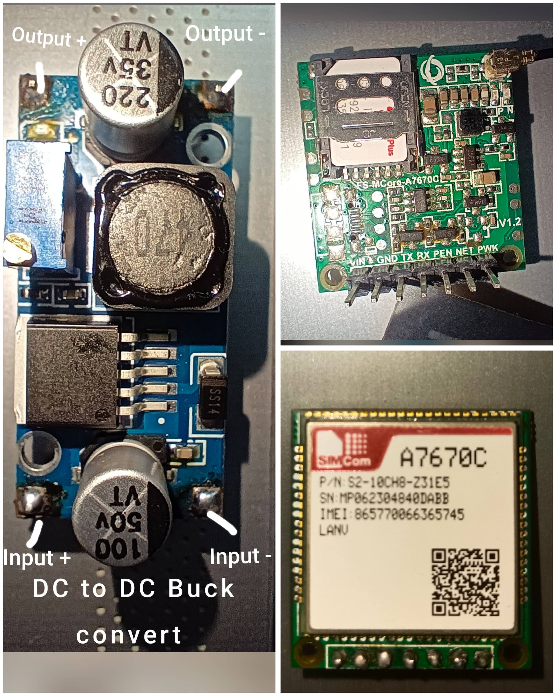
I am trying to interface an ESP32 with a SIMCOM A7670C GSM/4G module, but I am not receiving proper responses to AT commands. Sometimes I only see ATREADY: 1, but after that no reply comes. In Some time It's Showing Continuously ATREADY: 1 Response.
Here are my details:
Hardware Setup: -
- GSM Module: SIMCOM A7670C (LTE module, version E)
- MCU: ESP32 Devkit
- Power Supply:
- DC-DC Buck Converter set to 4.0V output
- Multimeter readings: 1.6A current consumption when module is ON
- Voltage remains stable at ~4.0V during operation
- Connections:
- VCC → 4.0V from buck converter
- GND → Common ground with ESP32
- TX (A7670) → RX (GPIO16 of ESP32)
- RX (A7670) → TX (GPIO17 of ESP32)
- PEN → 3.3V
- NETLIGHT → LED (blinks continuously)
- PWRKEY → GPIO4 of ESP32 (pulled LOW to turn ON)
Software Setup: -
Arduino IDE, Code 1 Serial configured at 115200 baud:
#include <SoftwareSerial.h>

SoftwareSerial sim(21,22);

void setup() {
  Serial.begin(115200);                          // USB Serial Monitor

  Serial.println("=== GSM AT Command Test Start ===");
  delay(2000);

  sim.println("AT");          // Basic Test
  delay(1000);
  sim.println("ATI");         // Module Info
  delay(1000);
  sim.println("AT+CPIN?");    // SIM Status
  delay(1000);
  sim.println("AT+CREG?");    // Network Status
}

void loop() {
  if (sim.available()) {
    Serial.write(sim.read());
  }
  if (Serial.available()) {
    sim.write(Serial.read());
  }
}
Arduino IDE, Code 2 Serial configured at 115200 baud:
#include <HardwareSerial.h>

HardwareSerial modem(1);

#define PWRKEY 4

void setup() {
  // put your setup code here, to run once:
  pinMode(PWRKEY, OUTPUT);
  digitalWrite(PWRKEY, HIGH);
  delay(100);
  digitalWrite(PWRKEY, LOW);
  delay(1500);
  digitalWrite(PWRKEY, HIGH);

  Serial.begin(115200);
  modem.begin(115200, SERIAL_8N1, 21,22);
  Serial.print("Sending AT... ");
  delay(3000);
  modem.println("AT");

}

void loop() {
  // put your main code here, to run repeatedly:
  if(modem.available()){
    Serial.write(modem.read());
  }
  if(Serial.available()){
    modem.write(Serial.read());
  }

}
Arduino IDE, Code 3 Manual AT Command Sending From Serial Monitor Serial configured at 115200 baud:
#include <HardwareSerial.h>
HardwareSerial testSerial(1);

void setup() {
  Serial.begin(115200);
  testSerial.begin(115200, SERIAL_8N1, 21,22); // RX=16, TX=17
  Serial.println("Type something below:");
}

void loop() {
  while (Serial.available()) {
    char c = Serial.read();
    testSerial.write(c);   // USB → TX
  }
  while (testSerial.available()) {
    char c = testSerial.read();
    Serial.write(c);       // RX → USB
  }
}
I am Trying These 3 Code One By One To Check Module is Working or not
Problem Observed
- When powered, the NETLIGHT LED keeps blinking continuously (does not stabilize).
- Sometimes I see
ATREADY: 1message, but when I sendAT, no OK response comes. - Without breadboard, the module powers ON once, then LED stops blinking and never comes back ON.
- With breadboard + buck converter, LED blinks continuously but still no AT responses.
- Power seems enough (4.0V, 1.6A measured).
My Questions
- Any Power Supply Issue the Module Is Continue Reset or not Connecting to Network.
- Is my wiring correct (specially PWRKEY and PEN pins)?
- Do I need a different sequence to power ON A7670?
- Why is the module only sending
ATREADY: 1but not responding toATcommands? - Is my buck converter sufficient, or should I use a Li-Ion battery for better current stability?
Any help, guidance, or working example code for ESP32 + A7670 would be greatly appreciated 
 Thanks in advance!

